20.2 Connection Cable
20.2.2 RS-485 cable
20 - 11
17
CONNECTION TO
ALLEN-BRADLEY PLC
18
CONNECTION TO
SIEMENS PLC
19
MICROCOMPUTER
CONNECTION
20
CONNECTION TO OMRON
TEMPERATURE
CONTROLLER
21
CONNECTION TO
YAMATAKE TEMPERATURE
CONTROLLER
22
CONNECTION TO RKC
TEMPERATURE
CONTROLLER
23
CONNECTION TO
FREQROL SERIES
INVERTER
24
SERVO AMPLIFIER
CONNECTION
20.2.2 RS-485 cable
The following shows the connection diagrams and connector specifications of the RS-485 cable used for
connecting the GOT to a temparature controller.
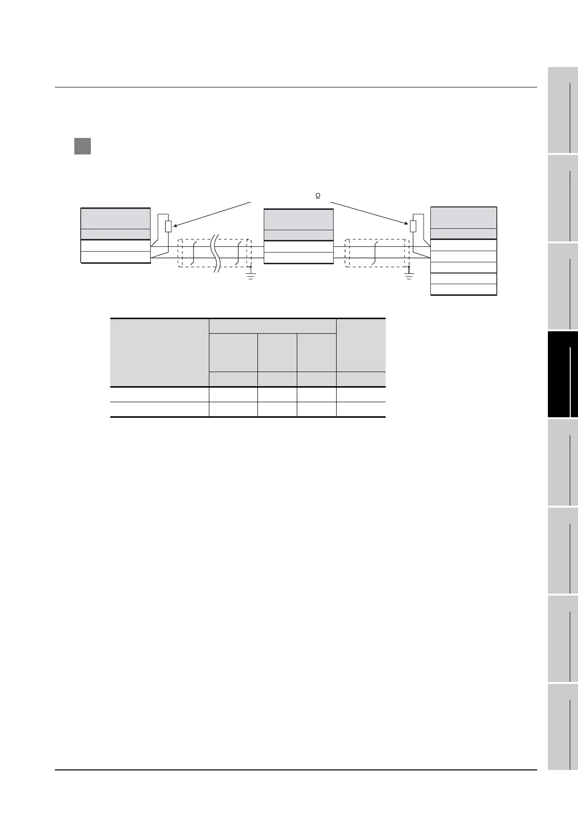
1 Connection diagram
(1) RS-485 cable1)
*1 Pin No. of temperature controller differs depending on the model. Refer to the following table.
*2 Terminating resistor should be provided for a temperature controller and an interface converter which will be
terminals.
Signal name
Model of temperature controller
Interface
converter
(K3SC-10)
E5AN
E5EN
E5CN
E5GN E5ZN
Pin No. Pin No. Pin No. Pin No.
A(-) 12 6 24 8
B(+) 11 5 23 11
Terminating resistor (120 1/2W)*
2
A(-)
B(+)
Temperature
controller side
Signal name
A(-)
B(+)
Temperature
controller side
Signal name
*1 *1
A(-)
Interface converter
(K3SC-10)
B(+)
*1
Signal name

 Loading...


