27 - 80
27.4 Ethernet Connection
27.4.10 CNC Side Settings
27.4.10 CNC Side Settings
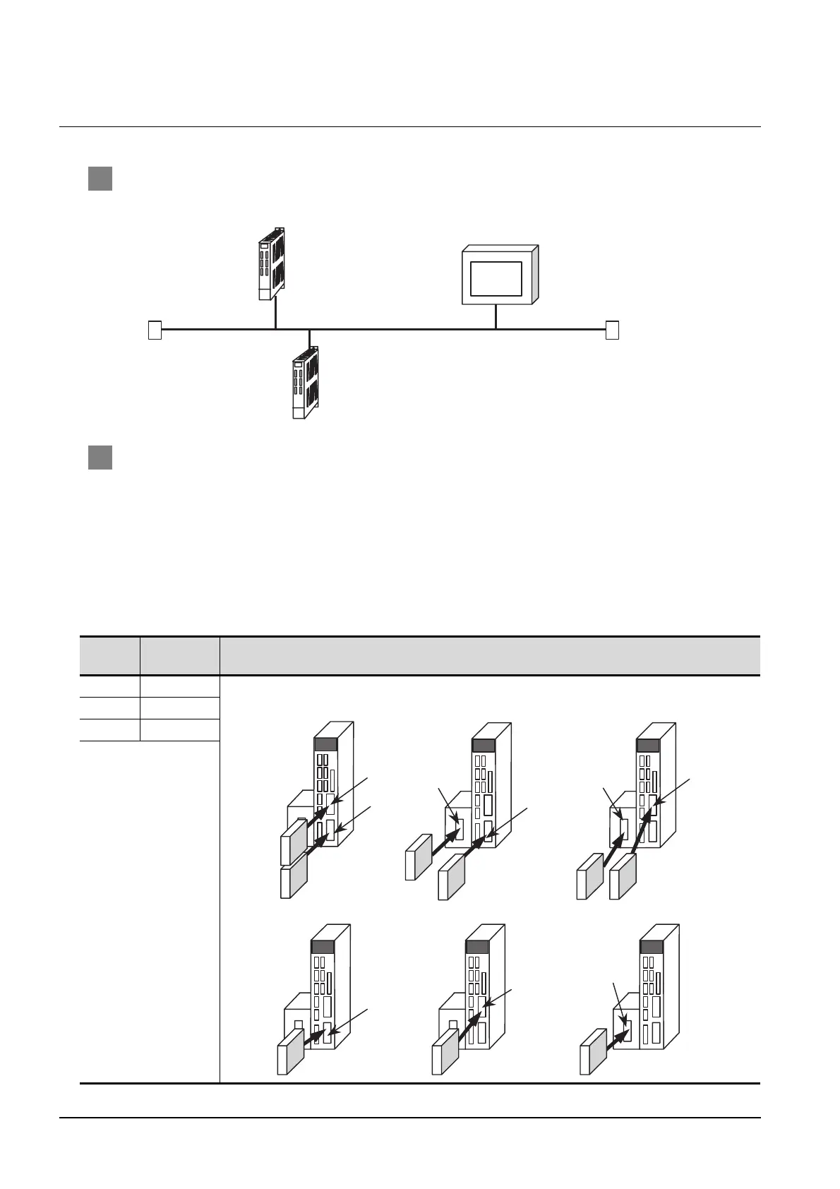
1 System configuration
The following shows the example of the system configuration when using the CNC monitor function.
2 Parameter setting
Set parameters related to Ethernet with MELSEC’s peripheral devices in the same way as
parameter setting of MELSEC CPU, and write them on CNC by PC.
(1) Network parameter setting
Set the network parameters by peripheral device and write them on CNC. An example of parameter
setting by GPPW is as follows.
Set the first I/O No. as follows according to the expansion slot to which the unit is inserted.
(a) Unit No.
Slot
position
Start I/O No. Mounting position of extension unit
EXT1 0200
EXT2 0280
EXT3 0300
Ethernet(192.168.1.xx)
<CNC-1>
[Communication with GOT]
N/W No. :239
PLC No. :2
IP address:192.168.1.2
<CNC-2>
N/W No. :239
PLC No. :3
IP address:192.168.1.3
<GOT>
N/W No. :1
PLC No. :1
IP address:192.168.1.1
EXT2
EXT1
Unit2
Unit1
EXT3
EXT1
EXT2
EXT3
EXT1
[When mounted in EXT2 only] [When mounted in EXT3 only]
EXT2
EXT3
[When mounted in EXT1 and EXT2] [When mounted in EXT1 and EXT3] [When mounted in EXT2 and EXT3]
[When mounted in EXT1 only]
Unit2
Unit2
Unit1
Unit1
Unit1
Unit1
Unit1

 Loading...


