6.1 System Configuration
6 - 3
1
OVERVIEW
2
BUS CONNECTION
3
DIRECT CONNECTION
TO CPU
4
COMPUTER LINK
CONNECTION
5
MELSECNET/10
CONNECTION (PLC TO
PLC NETWORK)
6
CC-Link CONNECTION
(INTELLIGENT DEVICE
STATION)
7
CC-Link CONNECTION
(Via G4)
8
ETHERNET
CONNECTION
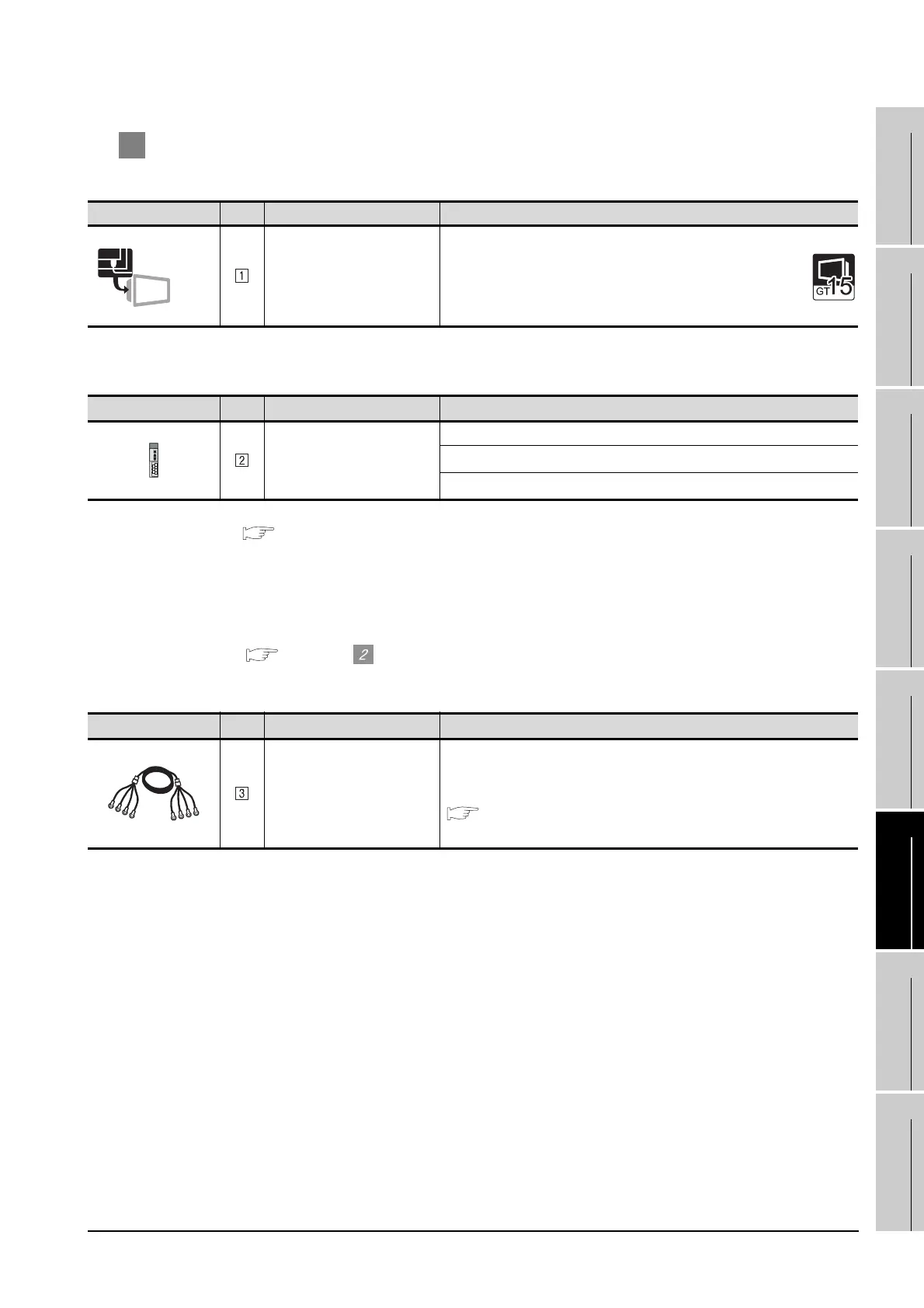
2 System equipment
(1) GOT
(2) PLC
*1 For the system configuration of the CC-Link module, refer to the following manuals.
• CC-Link System Master/Local Module User's Manual QJ61BT11N
• Control & Communication Link System Master/Local Module type AJ61QBT11/A1SJ61QBT11 User's
Manual
• Control & Communication Link System Master/Local Module type AJ61BT11/A1SJ61BT11 User's Manual
*2 The GOT can be performed transient transmission to only CC-Link modules of function version B or later and
software version J or later.
Section 6.4 For transient transmission
(3) Cable
Image No. Name Model name
CC-Link comunication unit
• Intelligent device station
GT15-75J61BT13-Z
Image No. Name Model name
CC-Link module
*1
QJ61BT11, QJ61BT11N
AJ61QBT11
*2
, A1SJ61QBT11
*2
AJ61BT11
*2
, A1SJ61BT11
*2
Image No. Name Model name
CC-Link dedicated cable
For the specifications and inquiries of the CC-Link dedicated cable, refer to the
following.
CC-Link Partner Association's home page: http://www.cc-link.org/
CC-Link
(Intelligent)

 Loading...


