9.4 PLC Side Setting
9.4.7 Connecting communication board, serial communication board (CQM1-SCB41)
9 - 51
9
CONNECTION TO
OMRON PLC
10
CONNECTION TO
KEYENCE PLC
11
CONNECTION TO
SHARP PLC
12
CONNECTION TO
TOSHIBA PLC
13
CONNECTION TO
HITACHI PLC
14
CONNECTION TO
MATSUSHITA PLC
15
CONNECTION TO
YASKAWA PLC
16
CONNECTION TO
YOKOGAWA PLC
9.4.7 Connecting communication board, serial communication board
(CQM1-SCB41)
1 Device settings
Write the following set values to devices of each PLC CPU and initialize each port using a peripheral
tool or DM monitor.
*1 Only transmission speeds available on the GOT side are shown.
*2 Set the same transmission speed as that of the GOT side.
For the transmission speed setting on the GOT side, refer to the following.
Section 9.3.3 Setting communication interface (Communication settings)
*3 Set the host link station No. according to the Host Address setting on the GOT side.
For the Host Address setting on the GOT side, refer to the following.
Section 9.3.3 Setting communication interface (Communication settings)
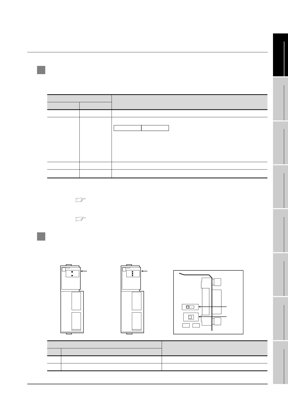
2 Setting DIP switches (C200HW-COM3 and C200HW-COM6 only)
Set the DIP switches when performing the RS-422 communications on the C200HW-COM3 and
C200HW-COM6.
Device name
Setting
Port B Port A
DM6550 DM6555 0001H (fixed)
DM6551 DM6556
DM6552 DM6557 0000 (fixed)
DM6553
*3
DM6558
*3
0000 to 0031
DIP switch
Settings
No. Item
SW1 RS-422/485 cable (2-wire/4-wire type) switching 4 (4-wire type)
SW2 Terminator ON/OFF 1 (no terminating resistor attached)
b15 to b8 b7 to b0
1) Transmission speed
*1*2
02H:4800bps
03
H:9600bps
04
H:19200bps
2)
1)
2) Frame format setting
03
H (fixed): The settings are:
Start bit :1 bit
Data length:7 bits
Stop bit :2 bits
Parity :Even bits
COMO3 A RS422/485
RDY
COMA
A
COMO6 A RS422/485
B RS232
RDY
COMA
COMB
A
SW2
SW1
Side view indicated by A
2
4
1
ON
C200HW-COM3 C200HW-COM6

 Loading...


