7.1 System Configuration
7.1.1 Connecting to QCPU (Q mode)
7 - 3
1
OVERVIEW
2
BUS CONNECTION
3
DIRECT CONNECTION
TO CPU
4
COMPUTER LINK
CONNECTION
5
MELSECNET/10
CONNECTION (PLC TO
PLC NETWORK)
6
CC-Link CONNECTION
(INTELLIGENT DEVICE
STATION)
7
CC-Link CONNECTION
(Via G4)
8
ETHERNET
CONNECTION
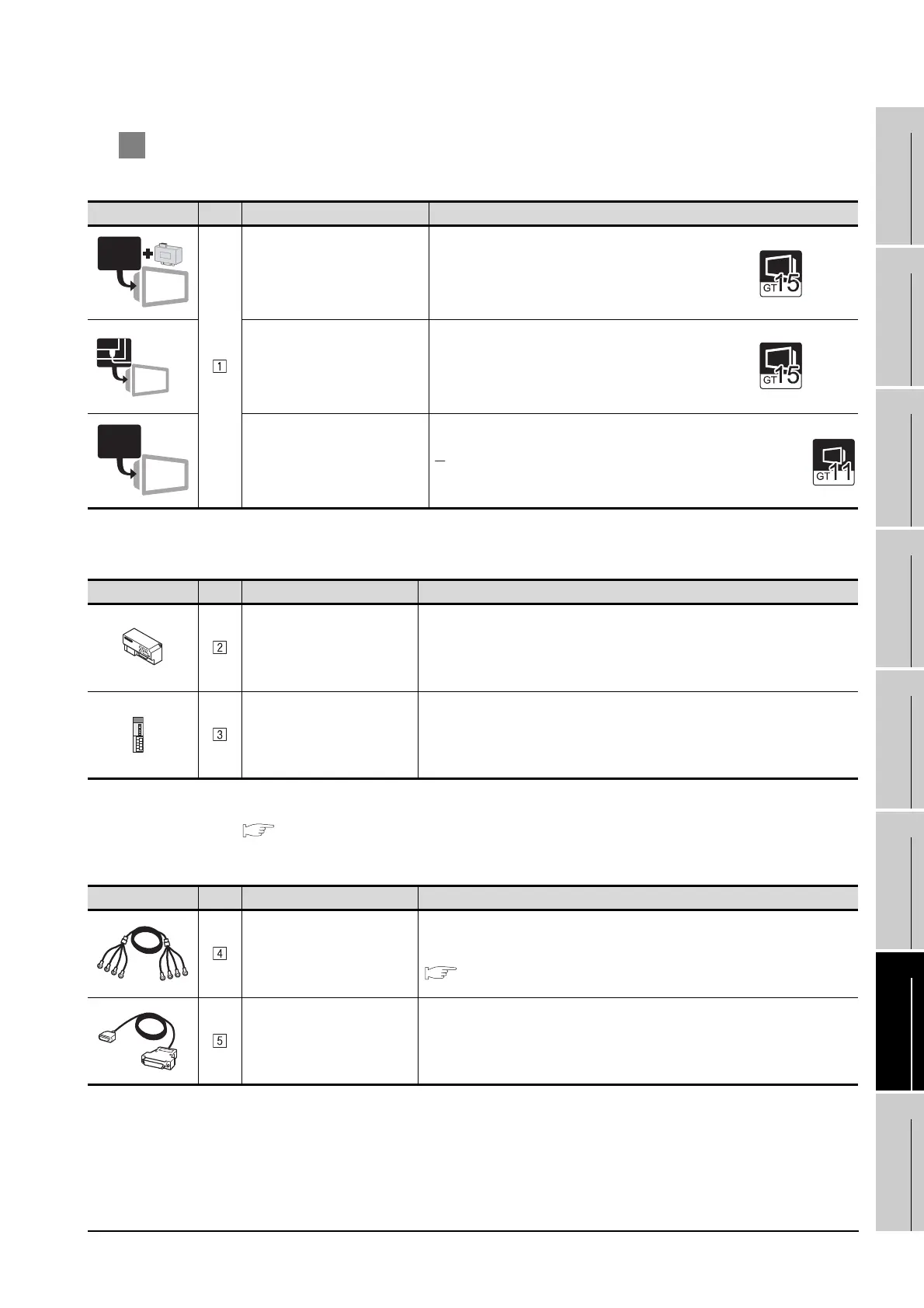
2 System equipment
(1) GOT
*1 Connect it to the RS-232 interface (built into GOT).
(2) PLC
*2 AJ65BT-G4 cannot be connected to the GOT.
*3 For the system configuration of the CC-Link module, refer to the following manual.
CC-Link System Master/Local Module User’s Manual QJ61BT11N
(3) Cable
Image No. Name Model name
RS-422 conversion unit
*1
• For RS-422 communication
GT15-RS2T4-9P
RS-422/485 Communication Unit
• For RS-422 communication
GT15-RS4-9S
RS-422 interface
• For RS-422 communication
(Built into GOT)
Image No. Name Model name
Peripheral connection module
*2
AJ65BT-G4-S3
CC-Link module
*3
QJ61BT11, QJ61BT11N
Image No. Name Model name
CC-Link dedicated cable
For the specifications and inquiries of the CC-Link dedicated cable, refer to the fol-
lowing.
CC-Link Partner Association's home page: http://www.cc-link.org/
RS-422 cable
GT01-C30R4-25P(3m), GT01-C100R4-25P(10m)
GT01-C200R4-25P(20m), GT01-C300R4-25P(30m)
RS-232
RS-422/485
RS-422

 Loading...


