8.3 PLC Side Setting
8.3.2 Connecting to Ethernet module (QnA Series)
8 - 25
1
OVERVIEW
2
BUS CONNECTION
3
DIRECT CONNECTION
TO CPU
4
COMPUTER LINK
CONNECTION
5
MELSECNET/10
CONNECTION (PLC TO
PLC NETWORK)
6
CC-Link CONNECTION
(INTELLIGENT DEVICE
STATION)
7
CC-Link CONNECTION
(Via G4)
8
ETHERNET
CONNECTION
8.3.2 Connecting to Ethernet module (QnA Series)
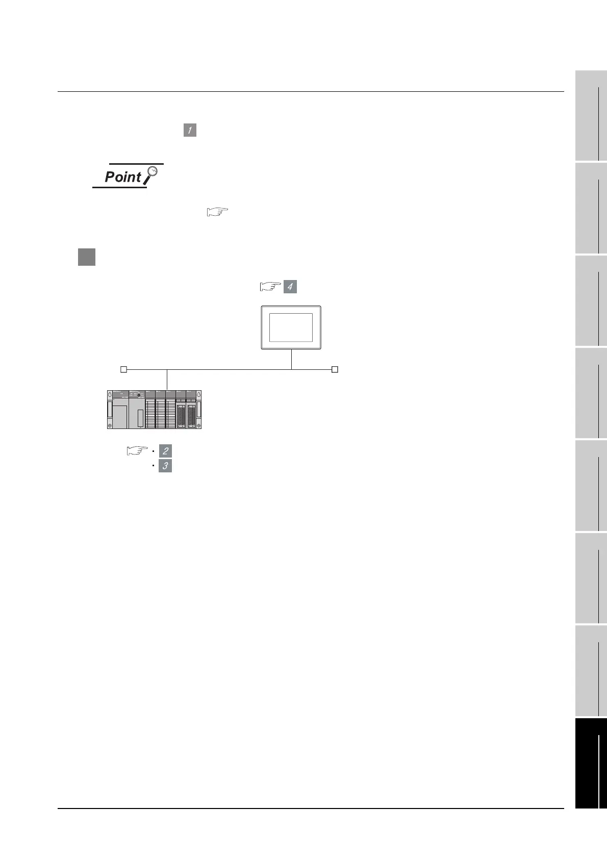
This section describes the settings of the GOT and Ethernet module (Q Series) given for the system
configuration shown at .
Ethernet module (QnA Series)
For details of the Ethernet module (QnA Series), refer to the following manual.
For QnA Ethernet Interface Module User’s Manual
1 System configuration
*1 The Ethernet module is mounted on the base unit slot 0.
The Start I/O No. of the Ethernet module is set to "0".
Switch setting of Ethernet module
<GOT>(The settings other than the following
are set to the default)
[Communication settings] and [Ethernet setting] of GT
Designer2
[Network parameter] of GX Developer
Network No.
PC No.
IP address
Port No.
Communication format
: 1
: 1
: 192.168.0.18
: 5001
: UDP(fixed)
Network No.
PC No.
IP address
Port No.
Communication format
: 1
: 2
: 192.168.0.19
: 5001
: UDP(fixed)
<Ethernet module> (The settings other than the following are
set to the default)
*1

 Loading...


