11 - 16
11.2 Connection Cable
11.2.1 RS-232 cable
11.2.1 RS-232 cable
The following shows the connection diagrams and connector specifications of the RS-232 cable used for
connecting the GOT to a PLC.
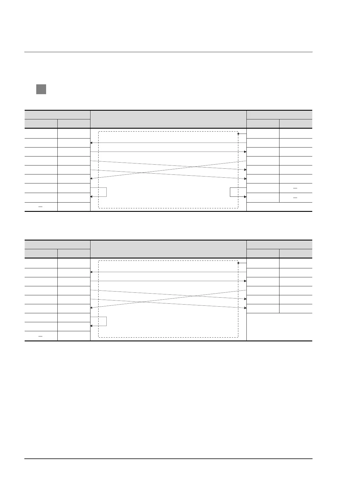
1 Connection diagram
(1) RS-232 cable 1)
*1 GT15: CD, GT11: NC
(2) RS-232 cable 2)
*2 GT15: CD, GT11, NC
GOT side
Cable connection and signal direction
SHARP product side
Signal name Pin No. Pin No. Signal name
CD/NC
*1
1 1FG
RD(RXD) 2 2SD(TXD)
SD(TXD) 3 3 RD(RXD)
ER(DTR) 4 4RTS
SG 5 5CTS
DR(DSR) 6 7SG
RS(RTS) 7 12
CS(CTS) 8 14
9
GOT side
Cable connection and signal direction
SHARP product side
Signal name Pin No. Pin No. Signal name
CD/NC
*2
1 1FG
RD(RXD) 2 2SD
SD(TXD) 3 4RD
ER(DTR) 4 8RTS
SG 5 12 CTS
DR(DSR) 6 7SG
RS(RTS) 7
CS(CTS) 8
9

 Loading...


