6.3 PLC Side Setting
6 - 19
1
OVERVIEW
2
BUS CONNECTION
3
DIRECT CONNECTION
TO CPU
4
COMPUTER LINK
CONNECTION
5
MELSECNET/10
CONNECTION (PLC TO
PLC NETWORK)
6
CC-Link CONNECTION
(INTELLIGENT DEVICE
STATION)
7
CC-Link CONNECTION
(Via G4)
8
ETHERNET
CONNECTION
6.3 PLC Side Setting
The GOT operates as the stations of which are shown below in the CC-Link system.
The switch settings and parameter settings of the PLC side (CC-Link module) are described in Section 6.3.1
to Section 6.3.3.
Number of stations occupied
The number of stations occupied is setting for determining number of link device
points (RX/RY/RWw/RWr) used by the GOT.
To use multiple numbers of link device points in the case of cyclic transmission
between the GOT and CC-Link module, set the number of stations occupied as the
exclusive station 4.
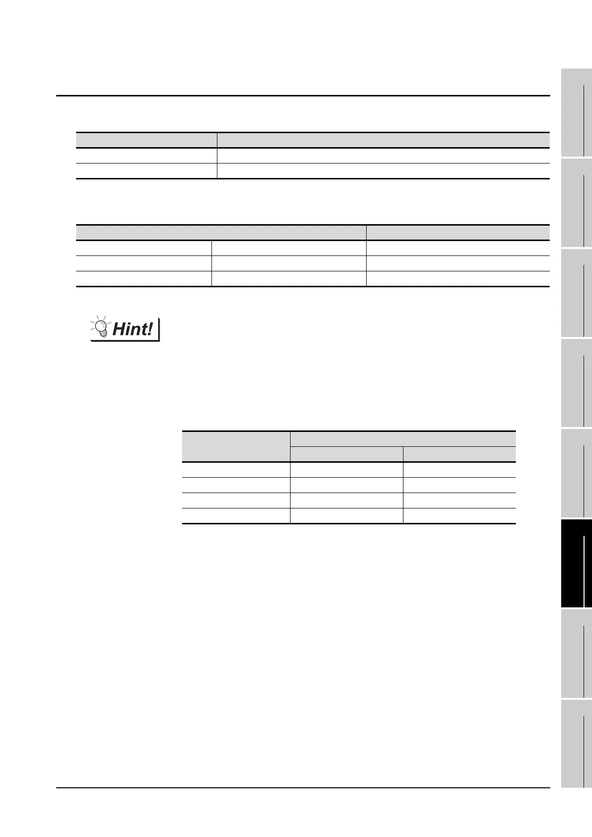
The number of link device points at the exclusive station 1 and 4 is shown below.
Station data Description
Station type Intelligent device station or Ver. 1 intelligent device station
Number of stations occupied Station 1 or Station 4
Model name Refer to
CC-Link module (Q Series) QJ61BT11, QJ61BT11N Section 6.3.1
CC-Link module (QnA Series) AJ61QBT11, A1SJ61QBT11 Section 6.3.2
CC-Link module (A Series) AJ61BT11, A1SJ61BT11 Section 6.3.3
Link device
Number of stations occupied
Exclusive station Exclusive of station 4
Remote input (RX) 32 points 128 points
Remote output (RY) 32 points 128 points
Remote registor (RWw) 4 points 16 points
Remote registor (RWr) 4 points 16 points

 Loading...


