19 - 28
19.5 Message Formats
19.5.3 Formats 1, 2 (GOT-A900 series microcomputer connection)
19.5.3 Formats 1, 2 (GOT-A900 series microcomputer connection)
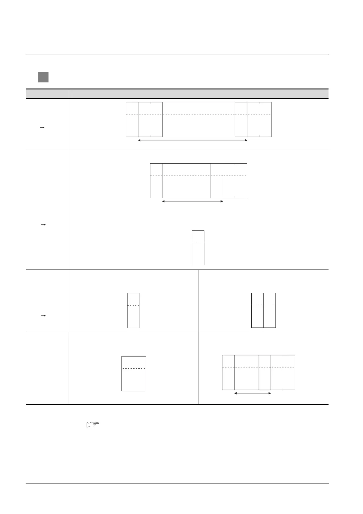
1 Basic format of data communication
*1 Set the number of interrupt data bytes at "Communication Detail Settings" in GT Designer2.
For the setting of the number of interrupt data bytes, refer to the following.
Section 19.6.3 Setting communication interface (Communication settings)
Item Message format
Request message
(host GOT)
Response
message during
normal
communication
(GOT host)
(1) During processing of read commands
(2) During processing of write commands
Response
message during
faulty
communication
(GOT host)
(format 1: GOT-A900 series microcomputer connection
(format 1))
(format 2: GOT-A900 series microcomputer connection
(format 2))
During interrupt
output
(format 1: GOT-A900 series microcomputer connection
(format 1))
(format 2: GOT-A900 series microcomputer connection
(format 2))
Sum check is performed in this range.
(H) (L)
Command Data
02
H
STX
03
H
ETX
(H) (L)
Sum
Check
Sum check is performed in this range.
Data
02
H
STX
03
H
ETX
(H) (L)
Sum
Check
06H
ACK
15H
NAK
15H
NAK
Error
Code
Output value
1/2/4
bytes
*1
Sum check is performed in this range.
02
H
STX
03
H
ETX
(H) (L)
Sum check
Output value
1/2/4
bytes
*1

 Loading...


