19.5 Message Formats
19.5.7 Formats 14, 15 (GOT-F900 series microcomputer connection)
19 - 59
17
CONNECTION TO
ALLEN-BRADLEY PLC
18
CONNECTION TO
SIEMENS PLC
19
MICROCOMPUTER
CONNECTION
20
CONNECTION TO OMRON
TEMPERATURE
CONTROLLER
21
CONNECTION TO
YAMATAKE TEMPERATURE
CONTROLLER
22
CONNECTION TO RKC
TEMPERATURE
CONTROLLER
23
CONNECTION TO
FREQROL SERIES
INVERTER
24
SERVO AMPLIFIER
CONNECTION
19.5.7 Formats 14, 15 (GOT-F900 series microcomputer connection)
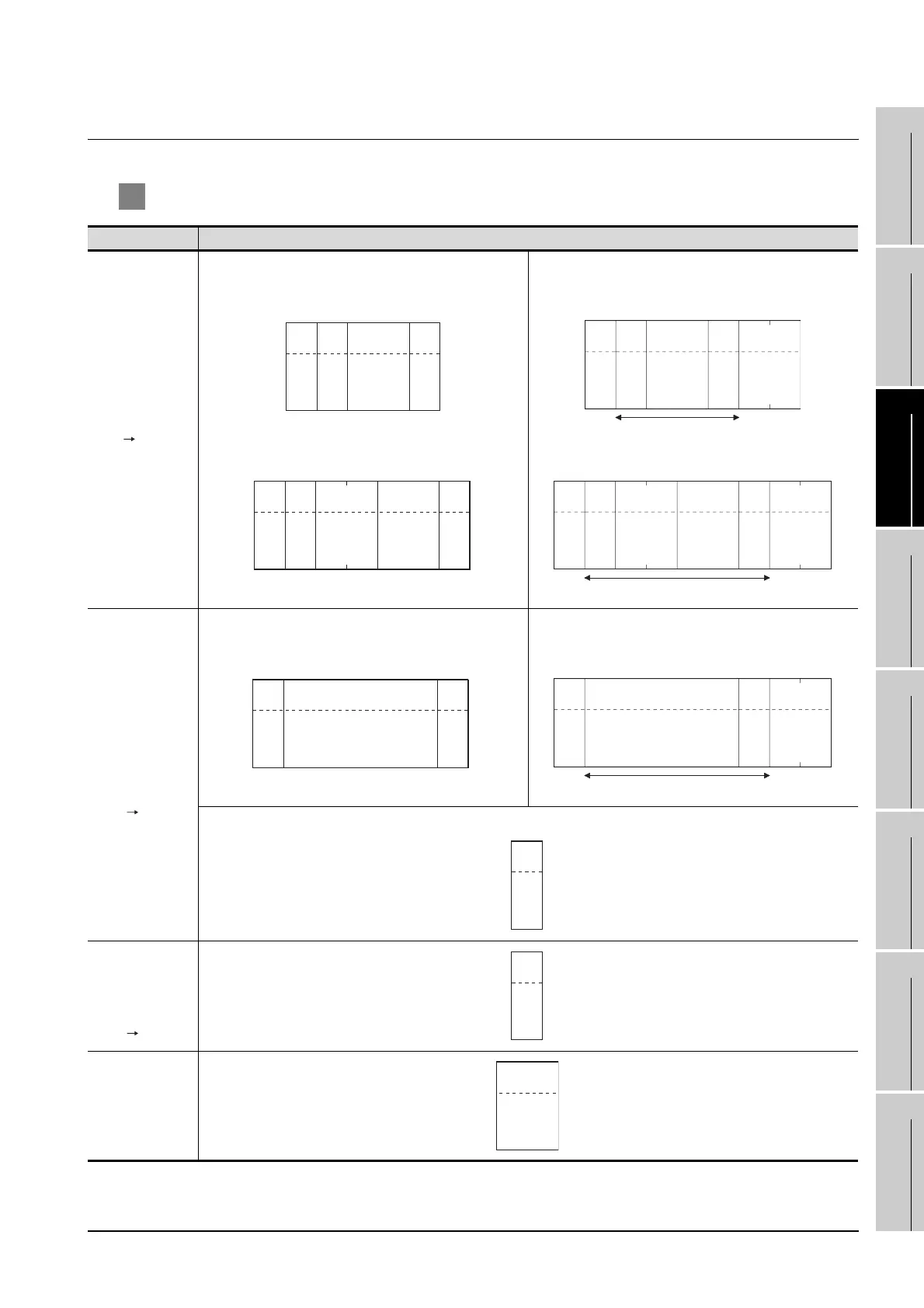
1 Basic format of data communication
*1 Set the number of interrupt data bytes at "Communication Details Settings" on GT Designer2.
For details of setting the number of interrupt data bytes, refer to the following.
Item Message format
Request message
(host GOT)
(format 14: GOT-F900 series microcomputer connection
(format 1))
(1) w/out station No.
(format 15: GOT-F900 series microcomputer connection
(format 2))
(1) w/out station No.
(2) w/ station No. (2) w/station No.
Response
message during
normal
communication
(GOT host)
(1) During processing of read commands
(format 14: GOT-F900 series microcomputer connection
(format 1))
(format 15: GOT-F900 series microcomputer connection
(format 2))
(2) During processing of write commands
Response
message during
faulty
communication
(GOT host)
During interrupt
output
02H
STX
0D
H
CRData
Com-
mand
Sum check is performed in this range.
02H
STX
03
H
ETX
(H) (L)
Sum
Check
Data
Com-
mand
02H
STX
0D
H
CRData
(H) (L)
Station No.
Com-
mand
Sum check is performed in this range.
02
H
STX
03H
ETX
(H) (L)
Sum
Check
Data
(H) (L)
Station No.
Com-
mand
02H
STX
0D
H
CR
Data
Sum check is performed in this range.
02
H
STX
03
H
ETX
(H) (L)
Sum
Check
Data
06H
ACK
15H
NAK
Output
value
1/2/4
bytes
*1

 Loading...


