4.1 System Configuration
4.1.5 Connecting to AnCPU type
4 - 13
1
OVERVIEW
2
BUS CONNECTION
3
DIRECT CONNECTION
TO CPU
4
COMPUTER LINK
CONNECTION
5
MELSECNET/10
CONNECTION (PLC TO
PLC NETWORK)
6
CC-Link CONNECTION
(INTELLIGENT DEVICE
STATION)
7
CC-Link CONNECTION
(Via G4)
8
ETHERNET
CONNECTION
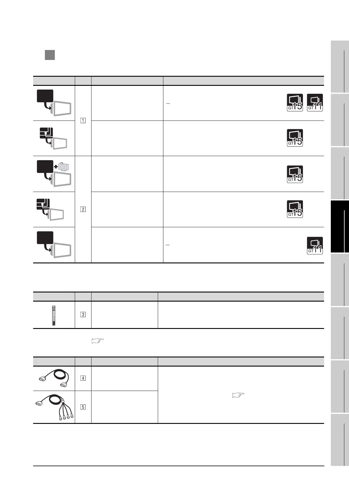
2 System equipment
(1) GOT
*1 Connect it to the RS-232 interface (built into GOT).
(2) PLC
*2 For the system configuration on the computer link module side, refer to the following manual.
Computer Link Module (Com. link func./Print. func. ) User’s Manual
(3) Cable
Image No. Name Model name
RS-232 interface
• For RS-232 communication
(Built into GOT)
RS-232 Communication Unit
• For RS-232 communication
GT15-RS2-9P
RS-422 conversion unit
*1
• For RS-422 communication
GT15-RS2T4-9P
RS-422/485 Communication Unit
• For RS-422 communication
GT15-RS4-9S
RS-422 interface
• For RS-422 communication
(Built into GOT)
Image No. Name Model name
Computer link module
*2
AJ71UC24
Image No. Name Model name
RS-232 cable 2)
(To be prepared by the user. Section 4.2 Connection Cable)
RS-422 cable
RS-232
RS-232
RS-232
RS-422/485
RS-422

 Loading...


