19.6 Preparatory Procedures for Monitoring
19.6.7 Checking for normal monitoring
19 - 85
17
CONNECTION TO
ALLEN-BRADLEY PLC
18
CONNECTION TO
SIEMENS PLC
19
MICROCOMPUTER
CONNECTION
20
CONNECTION TO OMRON
TEMPERATURE
CONTROLLER
21
CONNECTION TO
YAMATAKE TEMPERATURE
CONTROLLER
22
CONNECTION TO RKC
TEMPERATURE
CONTROLLER
23
CONNECTION TO
FREQROL SERIES
INVERTER
24
SERVO AMPLIFIER
CONNECTION
19.6.7 Checking for normal monitoring
1 Write data to virtual devices inside GOT.
Send a message from the host to the GOT, and confirm that the values are stored in the virtual devices
inside the GOT.
( Section 19.7 System Configuration Examples)
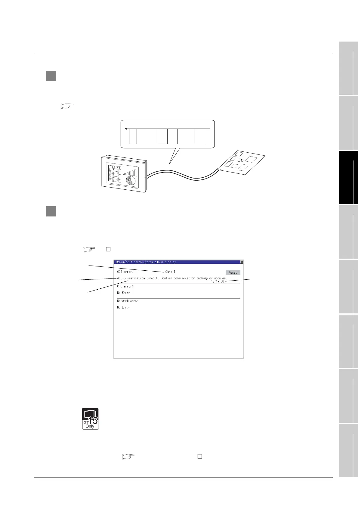
2 Check for errors occurring on the GOT.
Presetting the system alarm to project data allows you to identify errors occurred on the GOT, PLC
CPU, servo amplifier and communications.
For details on the system alarm, refer to the following manual.
GT User’s Manual (When using GT15)
Advanced alarm popup display
With the advanced alarm popup display function, alarms are displayed as a popup
display regardless of whether an alarm display object is placed on the screen or not
(regardless of the display screen).
Since comments can be flown from right to left, even a long comment can be
displayed all.
For details of the advanced popup display, refer to the following manual.
GT Designer2 Version Screen Design Manual
Microcomputer boa
Write command
S
T
X
RW
0163000A0100 0362
E
T
X
D3
Error code
Communication
Channel No.
Error message
Time of occurrence
(Displayed only for errors)

 Loading...


