7 - 2
7.1 System Configuration
7.1.1 Connecting to QCPU (Q mode)
7.1 System Configuration
Select a system configuration suitable for your application.
(1) PLC CPU QCPU (Q mode) that can be monitored in CC-Link (via G4) can be
monitored.
QnACPU, ACPU or QCPU (A mode) cannot be monitored.
(2) Conventions used in this section
Numbers (e.g. ) of System configuration and connection conditions
correspond to the numbers (e.g. ) of System equipment.
Use these numbers as references when confirming models and applications.
7.1.1 Connecting to QCPU (Q mode)
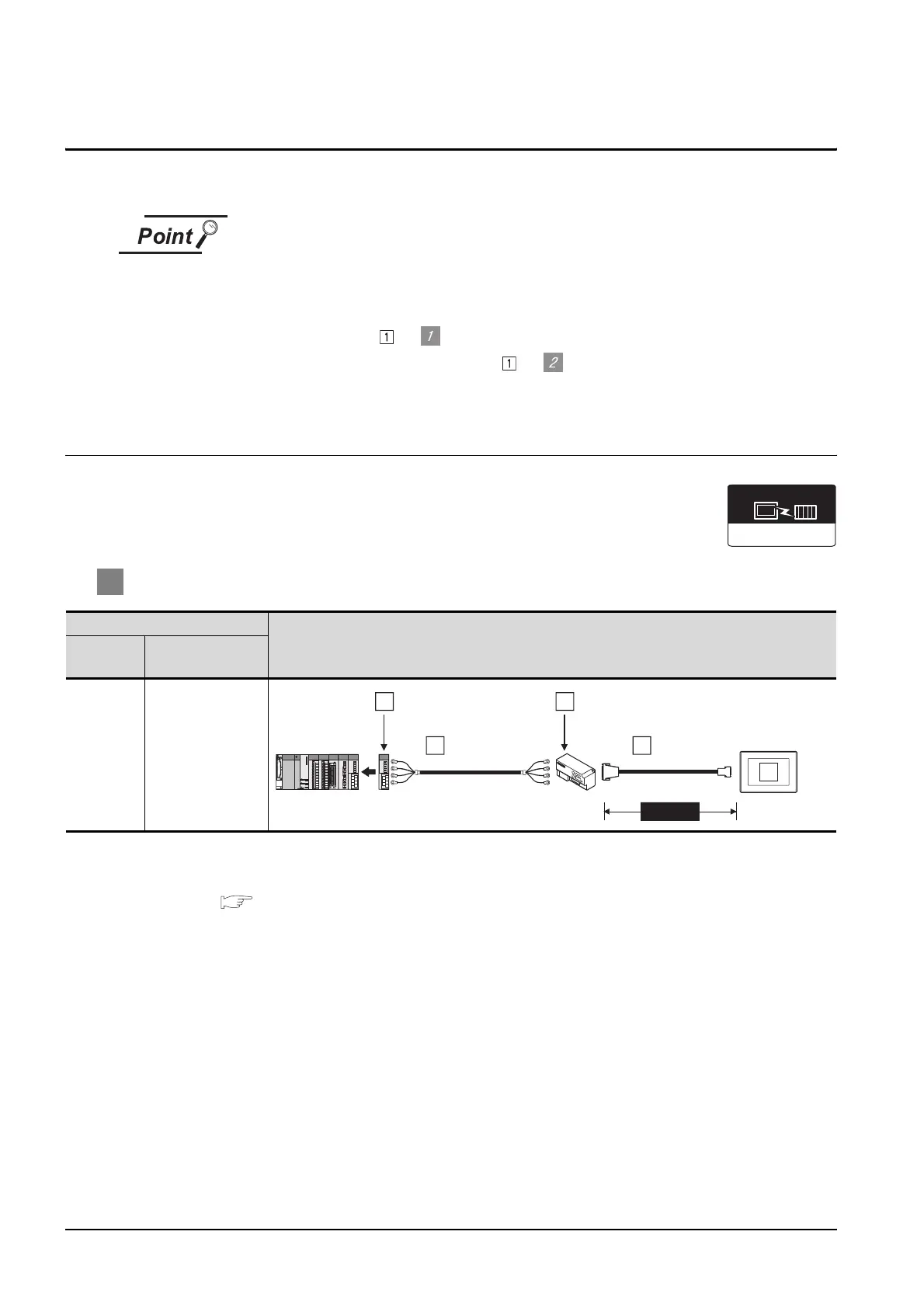
1 System configuration and connection conditions
*1 Max. overall extension cable length and the cable length between stations vary depending on the cable type to
be used and the transmission speed.
For details, refer to the following manual.
CC-Link System Master/Local Module User’s Manual QJ61BT11N
Connection conditions
System configuration
Number of
GOTs
Distance
1*1
CC-Link (G4)
Communication driver
RS-422 cable
5
1
CC-Link module
3
Peripheral connection module
2
CC-Link dedicated
cable
4
MAX30m

 Loading...


