27 - 56
27.3 CC-Link Connection (Intelligent Device Station)
27.3.9 Checking for normal monitoring
27.3.9 Checking for normal monitoring
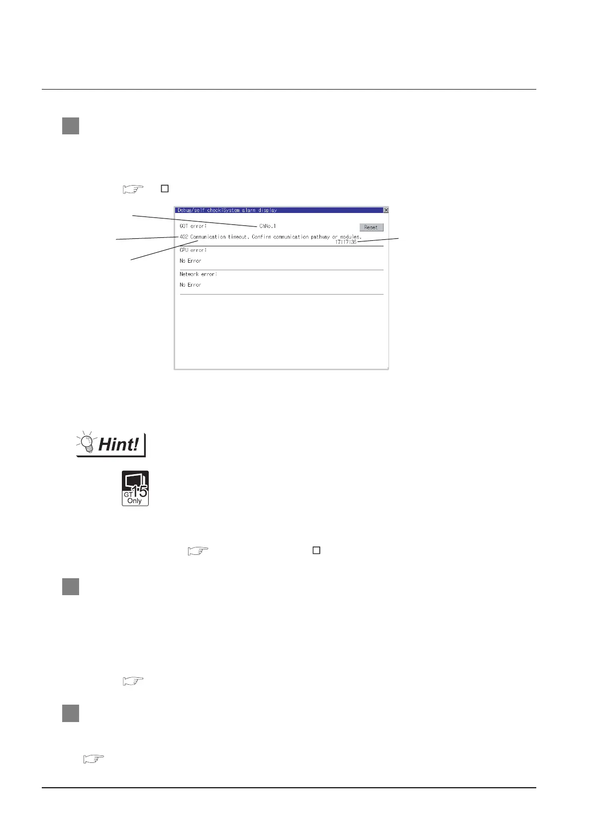
1 Check for errors occurring on the GOT.
Presetting the system alarm to project data allows you to identify errors occurred on the GOT, PLC
CPU, servo amplifier and communications.
For details on the system alarm, refer to the following manual.
GT User’s Manual (When using GT15)
Advanced alarm popup display
With the advanced alarm popup display function, alarms are displayed as a popup
display regardless of whether an alarm display object is placed on the screen or not
(regardless of the display screen).
Since comments can be flown from right to left, even a long comment can be
displayed all.
For details of the advanced popup display, refer to the following manual.
GT Designer2 Version Screen Design Manual
2 Checking the wiring state of the CC-Link dedicated cable
Check if the CC-Link dedicated cable is connected correctly to all the modules in the CC-Link system.
Perform the line test from the master station of the CC-Link System to check the wiring state of the CC-
Link dedicated cable.
For the line testing method, refer to the following manuals.
For details of the parameter setting, refer to the following.
MELDAS C6/C64 NETWORK MANUAL BNP-B2373
3 Confirming the CNC side setting
When connecting the GOT, setting is required for the CNC side.
Confirm if the CNC side setting is correct.
Section 27.3.10 CNC Side Settings
Error code
Communication
Channel No.
Error message
Time of occurrence
(Displayed only for errors)

 Loading...


