14.2 Connection Cable
14 - 19
9
CONNECTION TO
OMRON PLC
10
CONNECTION TO
KEYENCE PLC
11
CONNECTION TO
SHARP PLC
12
CONNECTION TO
TOSHIBA PLC
13
CONNECTION TO
HITACHI PLC
14
CONNECTION TO
MATSUSHITAI PLC
15
CONNECTION TO
YASKAWA PLC
16
CONNECTION TO
YOKOGAWA PLC
14.2 Connection Cable
The RS-232 cable used for connection between the GOT and PLC needs to be prepared by the user.
The following shows each cable connection diagram and relevant connectors.
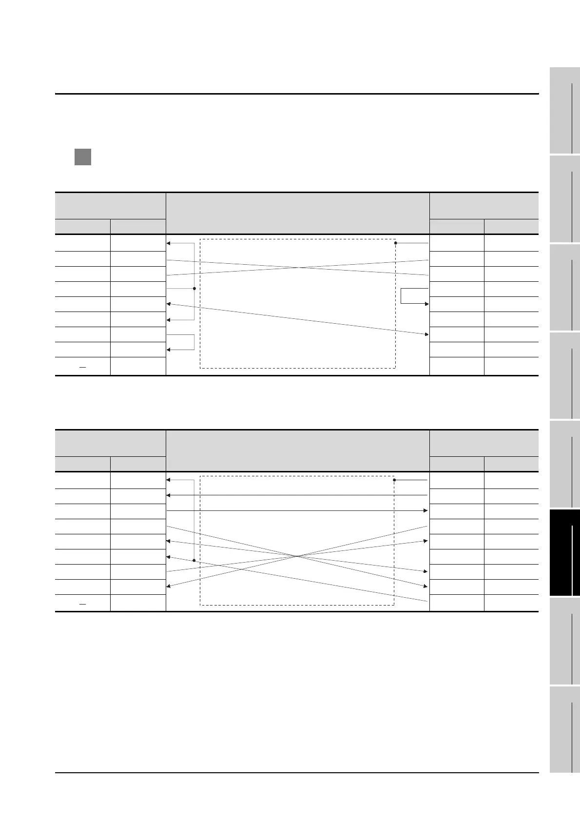
1 Connection diagram
(1) RS-232 cable 1) (between RS422/232C conversion adapter and GOT)
*1 GT15 : CD, GT11 : NC
(2) RS-232 cable 2) (between tool port and GOT (for FP10SH), between RS232C port and GOT and
between computer communication unit and GOT)
*2 GT15 : CD, GT11 : NC
GOT side
Cable connection and signal direction
Matsushita Electric Works, Ltd.
product side
Signal name Pin No. Pin No. Signal name
CD/NC
*1
1 1FG
RD(RXD) 2 2SD
SD(TXD) 3 3RD
ER(DTR) 4 4RS
SG 5 5CS
DR(DSR) 6 6DR
RS(RTS) 7 7SG
CS(CTS) 8 8CD
9 20 ER
GOT side
Cable connection and signal direction
Matsushita Electric Works, Ltd.
product side
Signal name Pin No. Pin No. Signal name
CD/NC
*2
1 1FG
RD(RXD) 2 2SD
SD(TXD) 3 3RD
ER(DTR) 4 4RS
SG 5 5CS
DR(DSR) 6 6RI
RS(RTS) 7 7SG
CS(CTS) 8 8CD
9 9ER

 Loading...


