11 - 38
11.4 PLC Side Setting
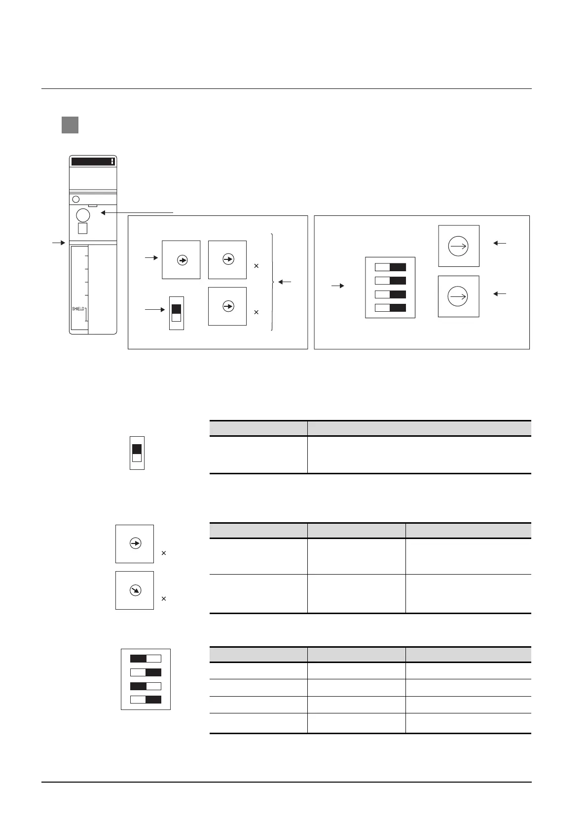
11.4.3 Connecting to the link unit (JW-31CM)
11.4.3 Connecting to the link unit (JW-31CM)
1 Switch setting of the link unit (JW-21CM)
Make setting for each switch.
(1) Module No. switch (SW8)
The module No. switch is not used for communication with the GOT.
(2) Terminator switch(SW7)
(3) Station number setting switch(SW1,CSW2)
(4) Operation mode setting switch(SW3)
Setting Description
ON
*1
Terminating resistor validated
*1 Turn on only for the terminal station.
Switch No. Setting Description
SW1
Station No. lower digit
(10
0
digit)
1 (fixed)
SW2
Station No. upper digit
(10
1
digit)
0 (fixed)
Switch No. Setting Description
SW3-1 OFF (fixed) Invalid
SW3-2 ON (fixed) 4-wire type
SW3-3 OFF (fixed) Invalid
SW3-4 ON (fixed) Even
UNIT No.
LT
ON
OFF
1
22
5
4
3
0
9
8
7
6
1
22
5
4
3
0
9
8
7
6
1
2
5
4
3
0
9
8
7
6
SW4
SW0
SW3
1234
ON
OFF
C
B
A
9
8
7
6
5
F
E
D
4
3
2
1
0
C
B
A
9
8
7
6
5
F
E
D
4
3
2
1
0
STA
No.
10
STA
No.
1
SHIELD
UNIT
No.
CM 30 RO
80 40 20 10 8 4 2 1
JW-21CM
TERF
L1
L2
L3
L4
FG
Inside the front panel
(3)
(5)
(6)
(1)
(4)
(2)
A
Side view indicated by A
LT
ON
OFF
1
22
5
4
3
0
9
8
7
6
1
22
5
4
3
0
9
8
7
6
STA
No.
10
STA
No.
1
SW3
1234
ON
OFF

 Loading...


