Home
Mitsubishi
Touch terminals
GOT1000 Series
Mitsubishi GOT1000 Series User Manual
4
of 1
of 1 rating
1216 pages
Give review
Manual
Specs
To Next Page
To Next Page
To Previous Page
To Previous Page
Loading...
14 - 28
14.3 Preparatory Procedures for Monitoring
14.3.4 Downloading project da
ta
14.3.4
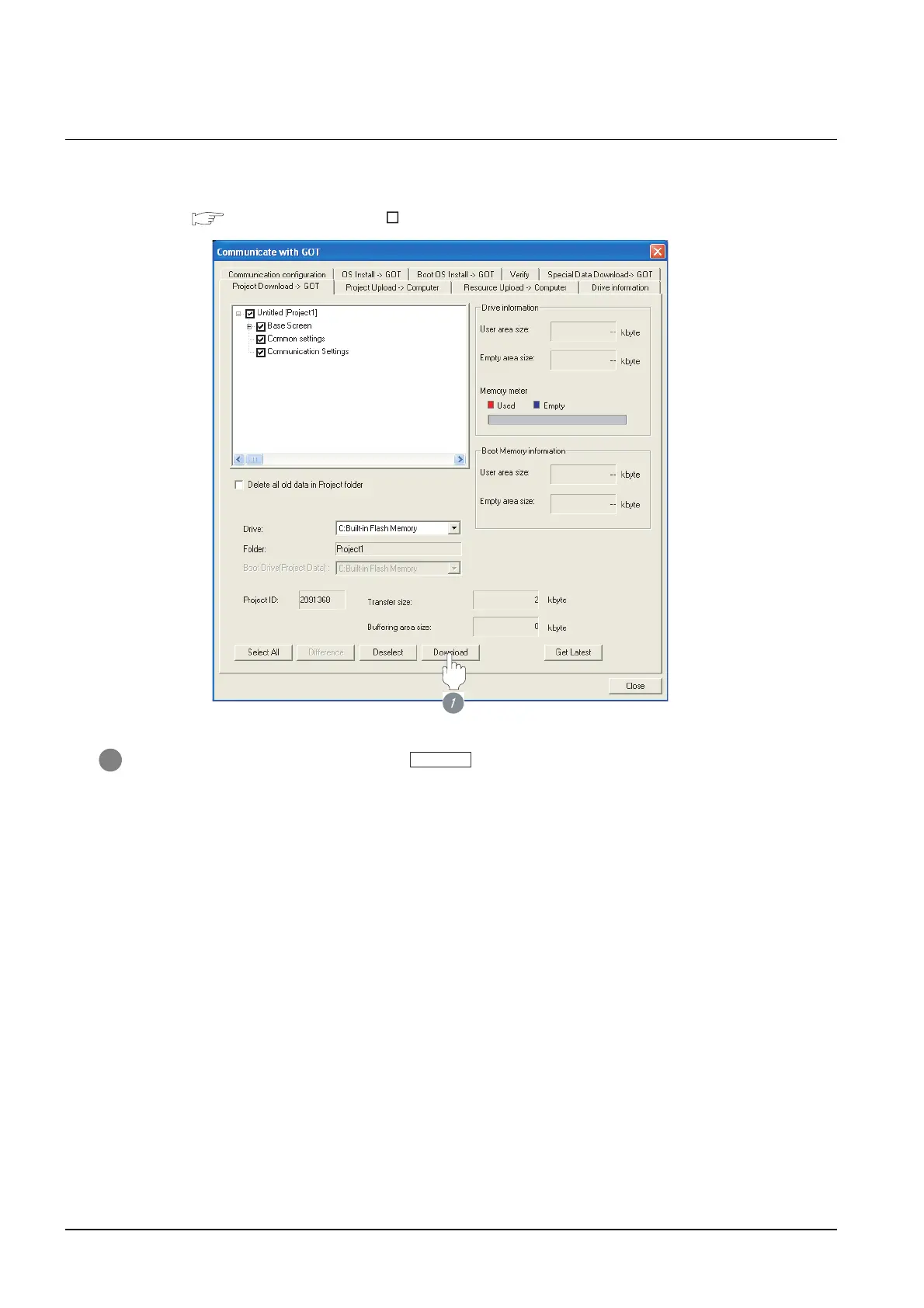
Downloading project data
Download pro
ject data to the
GOT
.
For how to download project dat
a, refer to th
e following manual.
G
T Designer2 V
ersion
Basic Operation/Dat
a T
ransfer Manual
1
Check the nece
ssary items and click the
button.
Download
Download
559
561
Table of Contents
Introduction
12
Safety Precautions
3
Revisions
10
Table of Contents
12
About Manuals
27
Abbreviations and Generic Terms in this Manual
28
How to Read this Manual
31
Overview
33
Connections and Functions Supported by GOT
36
Overall System Configurations
39
Mitsubishi Plc Connections
51
Bus Connection
53
System Configuration
54
Connecting to QCPU (Q Mode)
55
Connecting to Qnacpu or Ancpu Type
57
Connecting to Qnascpu or Anscpu Type
60
Connecting to A0J2HCPU
66
Connecting to Motion Controller CPU (Q Series)
67
Connecting to Motion Controller CPU (A273UCPU, A273UHCPU(-S3), A373UCPU(-S3))
68
System Configuration
69
Connecting to Motion Controller CPU (A171SHCPUN, A172SHCPUN, A173UHCPU(-S1))
72
Connection Cable
76
Preparatory Procedures for Monitoring
78
Installing os Onto GOT
79
Checking os Installation on GOT
80
Setting Communication Interface (Communication Settings)
81
Preparatory Procedures for Monitoring
82
Setting Communication Interface (Communication Settings)
85
Downloading Project Data
88
Attaching Communication Unit and Connecting Cable
89
Verifying GOT Recognizes Connected Equipment
91
Verifying GOT Recognizes Connected Equipment
92
Checking for Normal Monitoring
94
Precautions
96
Precautions
98
Communication Check Sheet
103
List of Functions Added by Version Upgrade
105
System Configuration
106
Connecting to QCPU
107
System Configuration
109
System Configuration
110
Connecting to FXCPU (FX 1S , FX 1N , FX 2N Series)
112
System Configuration
115
RS-232 Cable
117
System Configuration
118
System Configuration
119
RS-422 Cable
120
Connecting to Motion Controller CPU
121
Connection Cable
122
Connection Cable
123
Preparatory Procedures for Monitoring
124
Installing os Onto GOT
125
Checking os Installation on GOT
126
Setting Communication Interface (Communication Settings)
127
Setting Communication Interface (Communication Settings)
129
Downloading Project Data
130
Attaching Communication Unit and Connecting Cable
131
Attaching Communication Unit and Connecting Cable
132
RS-422 Cable
133
Verifying GOT Recognizes Connected Equipment
135
Verifying GOT Recognizes Connected Equipment
136
Checking for Normal Monitoring
137
Checking for Normal Monitoring
138
Precautions
139
List of Functions Added by Version Upgrade
140
PLC Side Setting
141
System Configuration
142
Connecting to QCPU (a Mode)
144
Connecting to Qnacpu Type
146
System Configuration
148
Connecting to Qnascpu Type
149
Connecting to Ancpu Type
152
System Configuration
153
Connecting to Anscpu Type
154
Connecting to Motion Controller CPU (Q Series)
156
Connection Cable
157
Connection Cable
158
RS-232 Cable
159
Precautions
160
RS-422 Cable
161
RS-422 Cable
162
Checking os Installation on GOT
163
Preparatory Procedure for Monitoring
164
Checking os Installation on GOT
165
Setting Communication Interface (Communication Settings)
166
Setting Communication Interface (Communication Settings)
167
Downloading Project Data
170
Attaching Communication Unit and Connecting Cable
171
Verifying GOT Recognizes Connected Equipment
175
Checking for Normal Monitoring
177
PLC Side Setting
179
Connecting Serial Communication Module (Q Series)
180
Connecting Serial Communication Module (Qna Series)
183
Connecting Computer Link Module
186
List of Functions Added by Version Upgrade
193
System Configuration
195
Connecting to the Coaxial Bus System
197
Installing os Onto GOT
199
Installing os Onto GOT
200
Checking os Installation on GOT
201
Setting Communication Interface (Communication Settings)
202
Downloading Project Data
206
Connecting to MELSECNET/H Network Module
216
Connecting to MELSECNET/10 Network Module (Qna Series)
221
Connecting to MELSECNET/10 Network Module (a Series)
228
System Configuration
238
System Configuration
239
Preparatory Procedures for Monitoring
240
Installing os Onto GOT
241
Preparatory Procedures for Monitoring
242
Setting Communication Interface (Communication Settings)
243
Setting Communication Interface (Communication Settings)
245
Downloading Project Data
247
Attaching Communication Unit and Connecting Cable
248
Attaching Communication Unit and Connecting Cable
249
Verifying GOT Recognizes Connected Equipment
250
Verifying GOT Recognizes Connected Equipment
251
Checking for Normal Monitoring
252
Checking for Normal Monitoring
253
PLC Side Settings
255
PLC Side Setting
256
List of Functions Added by Version Upgrade
279
Connecting to QCPU (Q Mode)
282
System Configuration
283
Connecting to Motion Controller CPU (Q Series)
284
Preparatory Procedures for Monitoring
285
Installing os Onto GOT
286
Checking os Installation on GOT
287
Setting Communication Interface (Communication Settings)
288
Downloading Project Data
290
Attaching Communication Unit and Connecting Cable
291
Verifying GOT Recognizes Connected Equipment
294
Checking for Normal Monitoring
296
Precautions
305
System Configuration Examples
314
Connecting to Ethernet Module (Q Series)
324
Connecting to Ethernet Module (Qna Series)
329
Connecting to Ethernet Module (a Series)
334
Precautions
340
List of Functions Added by Version Upgrade
341
System Configuration
346
System Configuration
348
Connecting to CQM1, CQM1H or CJ1
349
Connecting to C200HS, C200H, C200H or CS1
353
System Configuration
357
Connecting to C1000H/C2000H, CV500/CV1000/CV2000, CVM1
358
Connection Cable
361
RS-232 Cable
362
RS-232 Cable
363
RS-422 Cable
365
Preparatory Procedures for Monitoring
367
Installing os Onto GOT
368
Checking os Installation on GOT
369
Setting Communication Interface (Communication Settings)
370
Downloading Project Data
372
Attaching Communication Unit and Connecting Cable
373
Verifying GOT Recognizes Connected Equipment
377
Checking for Normal Monitoring
379
PLC Side Setting
381
Connecting CPM2A, CQM1, CQM1H, C200H or RS-232C Adapter
382
Connecting CJ1 or CS1
383
Connecting CV500/CV1000/CV2000 or CVM1
386
Connecting Connection Cable
388
Connecting Rack Type Host Link Unit
389
Connecting Serial Communication Unit
394
Connecting Communication Board, Serial Communication Board (CQM1-SCB41)
395
Connecting Serial Communication Board (CS1W-SCB21, CS1W-SCB41)
396
List of Functions Added by Version Upgrade
398
Connecton to Keyence Plc
399
System Configuration
400
RS-485 Cable
401
Connection Cable
407
Preparatory Procedures for Monitoring
415
PLC Side Setting
431
Connecting Multi-Communication Unit (KV-L20R, KV-L20)
432
List of Functions Added by Version Upgrade
434
Connecting to JW-21CU or JW-22CU
436
Connecting to JW-31CUH, JW-32CUH or JW-33CUH
439
Connecting to JW-50CUH
442
System Configuration
443
Connecting to JW-70CUH, JW-100CUH or JW-100CU
444
Connecting to Z-512J
447
Connection Cable
450
RS-422 Cable
452
Preparatory Procedures for Monitoring
455
Installing os Onto GOT
456
Checking os Installation on GOT
457
Setting Communication Interface (Communication Settings)
458
Downloading Project Data
460
Attaching Communication Unit and Connecting Cable
461
Verifying GOT Recognizes Connected Equipment
465
Checking for Normal Monitoring
467
Connecting to JW-22CU, JW-70CUH, JW-100CUH or JW-100CU
470
Connecting to JW-32CUH, JW-33CUH or Z-512J
471
Connecting to the Link Unit (JW-31CM)
472
Connecting to the Link Unit (JW-10CM or ZW-10CM)
474
List of Functions Added by Version Upgrade
476
Connecting to T2 (PU224), T2E, T2N, T3 or T3H
478
Connecting to Model 3000 (S2/S3)
481
Connecting to T2 (PU224), T2E or T2N
502
Connecting to T3 or T3H
503
List of Functions Added by Version Upgrade
504
Connecting to H-200 to 252 Series, H Series Board Type or EH-150 Series
509
Connection Cable
510
System Configuration
534
Connecting to FP1-C24C or FP1-C40C
536
Connecting to FP2 or FP2SH
538
Connecting to FP3
540
Connecting to FP5
542
Connecting to FP10 (S)
544
Connecting to FP10SH
546
Connecting to FP-M (C20TC) or FP-M (C32TC)
548
Connecting to FP SIGMA
549
Connection Cable
551
Preparatory Procedures for Monitoring
555
Installing os Onto GOT
556
Checking os Installation on GOT
557
Setting Communication Interface (Communication Settings)
558
Downloading Project Data
560
Attaching Communication Unit and Connecting Cable
561
Verifying GOT Recognizes Connected Equipment
563
Checking for Normal Monitoring
565
PLC Side Setting
567
List of Functions Added by Version Upgrade
569
Connecting to GL60S, GL60H, GL70H
574
Connecting to CP-9200SH
580
Connecting PC Link Module (F3LC01-1N, F3LC11-1N, F3LC11-2N)
634
Connecting PC Link Module (F3LC11-1F, F3LC12-1F)
636
Connecting PC Link Module (LC01-0N, LC02-0N)
638
Precautions
640
Connecting to Micrologix1000/1200/1500 Series
645
Connecting to a SIMATIC S7-200 Series
668
Preparatory Procedures for Monitoring
671
Checking os Installation on GOT
673
Setting Communication Interface (Communication Settings)
674
Downloading Project Data
677
Attaching Communication Unit and Connecting Cable
678
Verifying GOT Recognizes Connected Equipment
680
Checking for Normal Monitoring
682
PLC Side Setting
685
Setting on Servo Amplifier Side
692
Introduction
708
Default Chapter
709
List of Functions Added by Version Upgrade
709
Preparatory Procedures for Monitoring
710
Installing os Onto GOT
711
Checking os Installation on GOT
712
Setting Communication Interface (Communication Settings)
713
Downloading Project Data
714
Attaching Communication Unit and Connecting Cable
715
Verifying GOT Recognizes Connected Equipment
716
CONNECTION to OMRON TEMPERATURE CONTROLLER 20 - 1 to
717
CONNECTION to RKC TEMPERATURE CONTROLLER 22 - 1 to
718
Station No. Settings
719
Precautions
720
List of Functions Added by Version Upgrade
721
Attacing Communication Unit and Connecting Cable
722
About Manuals
723
Abbreviations and Generic Terms in this Manual
724
How to Read this Manual
727
Microcomputer Connection
732
System Configuration
734
Connection Cable
737
RS-422 Cable
739
Device Data Area
740
D Devices
741
R Devices
745
L Devices
746
M Devices
747
SD Devices
748
SM Devices
751
Message Formats
753
List of Commands
755
(A171Shcpun, A172Shcpun, A173Uhcpu(-S1))
758
Formats 3 to 6 (a Compatible 1C Frame)
771
Formats 7 to 10 (Qna Compatible 3C/4C Frame)
776
Formats 11 to 13 (Digital Electronics Corporation's Memory Link Method)
783
Formats 14, 15 (GOT-F900 Series Microcomputer Connection)
789
Preparatory Procedures for Monitoring
803
Installing os Onto GOT
804
Checking os Installation on GOT
805
Setting Communication Interface (Communication Settings)
806
Downloading Project Data
808
Attaching Communication Unit and Connecting Cable
809
Verifying GOT Recognizes Connected Equipment
813
Checking for Normal Monitoring
815
System Configuration Examples
817
Temperature Controller
821
List of Functions Added by Version Upgrade
823
System Configuration
824
Connecting to E5CN, E5GN
826
Connecting to E5ZN
828
Connection Cable
830
RS-232 Cable
831
RS-485 Cable
833
Preparatory Procedures for Monitoring
836
Installing os Onto GOT
837
Checking os Installation on GOT
838
Setting Communication Interface (Communication Settings)
839
Downloading Project Data
842
Attaching Communication Unit and Connecting Cable
843
Verifying GOT Recognizes Connected Equipment
846
Checking for Normal Monitoring
848
Temperature Controller Side Setting
850
Connecting to Interface Converter (K3SC-10)
851
Station NO. Settings
853
Precautions
854
List of Functions Added by Version Upgrade
855
System Configuration
858
Connecting to SDC15, SDC25/26 or SDC35/36
860
Connecting to SDC20/21
862
Connecting to SDC30/31
865
Connecting to SDC40A/40B/40G
867
Connection Cable
870
RS-232 Cable
871
RS-485 Cable
874
Preparatory Procedures for Monitoring
880
Installing os Onto GOT
881
Checking os Installation on GOT
882
Setting Communication Interface (Communication Settings)
883
Downloading Project Data
886
Attaching Communication Unit and Connecting Cable
887
Verifying GOT Recognizes Connected Equipment
890
Checking for Normal Monitoring
892
Temperature Controller Side Setting
894
Connecting SDC40A/40B/40G
895
Connecting SDC20/21, SDC30/31
896
Station NO. Settings
898
Precautions
899
List of Functions Added by Version Upgrade
900
Connecting to the MELSERVO-J2M Series
978
Connecting to the MELSERVO-J3 Series
980
Station NO. Settings
1002
Precautions
1007
List of Functions Added by Version Upgrade
1008
Printer Connection
1029
Direct Connection to CPU
1044
Connection Cable
1046
Preparatory Procedures for Monitoring
1048
Installing os Onto GOT
1049
Checking os Installation on GOT
1050
Setting Communication Interface (Communication Settings)
1051
Downloading Project Data
1053
Attaching Communication Unit and Connecting Cable
1054
Verifying GOT Recognizes Connected Equipment
1058
Checking for Normal Monitoring
1060
Precautions
1062
MELSECNET/10 Connection (PLC to PLC Network)
1063
Preparatory Procedures for Monitoring
1065
Installing os Onto GOT
1066
Checking os Installation on GOT
1067
Setting Communication Interface (Communication Settings)
1068
Downloading Project Data
1072
Attaching Communication Unit and Connecting Cable
1073
Verifying GOT Recognizes Connected Equipment
1077
Checking for Normal Monitoring
1079
CNC Side Settings
1080
Precautions
1083
CC-Link Connection (Intelligent Device Station)
1084
Preparatory Procedures for Monitoring
1086
Installing os Onto GOT
1087
Checking os Installation on GOT
1088
Setting Communication Interface (Communication Settings)
1089
Downloading Project Data
1093
Attaching Communication Unit and Connecting Cable
1094
Verifying GOT Recognizes Connected Equipment
1096
Checking for Normal Monitoring
1098
CNC Side Settings
1100
Precautions
1103
Ethernet Connection
1104
Preparatory Procedures for Monitoring
1106
Installing os Onto GOT
1107
Checking os Installation on GOT
1108
Setting Communication Interface (Communication Settings)
1109
Downloading Project Data
1114
Attaching Communication Unit and Connecting Cable
1115
Verifying GOT Recognizes Connected Equipment
1116
Checking for Normal Monitoring
1118
CNC Side Settings
1122
Precautions
1125
List of Functions Added by Version Upgrade
1126
Other Functions
1127
What Is Multi-Channel Function?
1130
System Configuration Examples
1131
Preparatory Procedures for Monitoring
1132
Installing os Onto GOT
1133
Checking os Installation on GOT
1134
Setting Communication Interface (Communication Settings)
1135
Downloading Project Data
1136
Attaching Option Function Borad/Communication Unit and Connecting Cable
1137
Verifying GOT Recognizes Connected Equipments
1138
Checking for Normal Monitoring
1140
Connected Equipment Side Settings
1142
List of Functions Added by Version Upgrade
1143
FA Transparent Function
1146
GX Developer
1147
FR Configurator
1149
Compatible Software
1151
Preparatory Procedure for Accessing
1153
Setting Communication Interface (Communication Settings)
1154
Attaching the Communication Unit and Connecting the Cable
1156
Verifying GOT Recognizes Connected Equipment
1157
Accessing the PLC by the GX Developer
1159
Accessing the Inverter by the FR Configurator
1162
Precautions
1164
When Using GX Developer
1167
When Using FR Configurator
1169
List of Functions Added by Version Upgrade
1170
4
Based on 1 rating
Ask a question
Give review
Questions and Answers:
Need help?
Do you have a question about the Mitsubishi GOT1000 Series and is the answer not in the manual?
Ask a question
Mitsubishi GOT1000 Series Specifications
General
Brand
Mitsubishi
Model
GOT1000 Series
Category
Touch terminals
Language
English
Related product manuals
Mitsubishi GOT1000 GT15
622 pages
Mitsubishi GOT1000 GT11
256 pages
Mitsubishi MELSEC-GOT F940
41 pages
Mitsubishi GOT1000
102 pages
Mitsubishi GOT2000 Series
520 pages
Mitsubishi GT2715XTBA
16 pages

 Loading...


