4.4 PLC Side Setting
4 - 39
1
OVERVIEW
2
BUS CONNECTION
3
DIRECT CONNECTION
TO CPU
4
COMPUTER LINK
CONNECTION
5
MELSECNET/10
CONNECTION (PLC TO
PLC NETWORK)
6
CC-Link CONNECTION
(INTELLIGENT DEVICE
STATION)
7
CC-Link CONNECTION
(Via G4)
8
ETHERNET
CONNECTION
4.4 PLC Side Setting
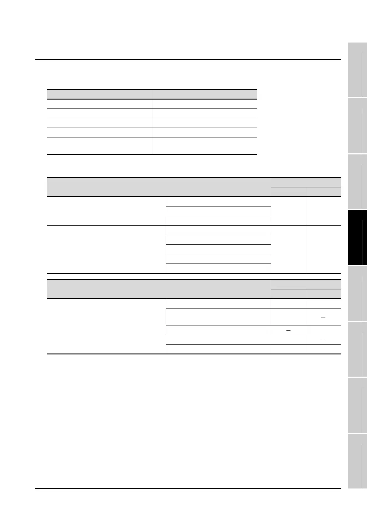
The GOT operates under the following transmission specifications when it is connected to a Mitsubishi PLC
in the computer link connection.
The PLC side settings (the serial communication module, computer link module) are explained in section
4.4.1 to 4.4.3.
Transmission specifications Setting
Data bit 8 bits
Parity bit Yes (Odd)
Stop bit 1 bit
Sum check Yes
Transmission speed
Set the same transmission speed on both the
GOT and the PLC.
Model
Connection channel
CH1 CH2
Serial communication module
(Q Series)
QJ71C24N, QJ71C24
Section 4.4.1 Section 4.4.1QJ71C24N-R2, QJ71C24-R2
QJ71C24N-R4
Serial communication module
(QnA Series)
AJ71QC24N, AJ71QC24
Section 4.4.2 Section 4.4.2
AJ71QC24N-R2, AJ71QC24-R2
AJ71QC24N-R4, AJ71QC24-R4
A1SJ71QC24N, A1SJ71QC24
A1SJ71QC24N-R2, A1SJ71QC24-R2
Model
Connection interface
RS-232 RS-422
Computer link module
AJ71UC24 Section 4.4.3 Section 4.4.3
A1SJ71UC24-R2, A1SJ71UC24-PRF,
A1SJ71C24-R2, A1SJ71C24-PRF
Section 4.4.3
A1SJ71UC24-R4, A1SJ71C24-R4 Section 4.4.3
A1SCPUC24-R2 Section 4.4.3
A2CCPUC24, A2CCPUC24-PRF Section 4.4.3 Section 4.4.3

 Loading...


