#
Turn thering of cargotie-down ring B untilit
is parallel to thelongitudinal axis of cargo tie-
down ring C.
#
Holdcargo tie-down ring C between the
indexfinger andmiddlefinger andplace your
thumb through thering of cargotie-down ring
B and ontothe centralpressurepoint.
#
Use your thumb to push thelocking pin down
as farasitwillgo.
#
Push cargo tie-down ring C nearthe load
through thenotches on rack rail 2 and move
it approximately 0.5 in (12mm).
#
Remove your thumb from thepressurepoint
and slide cargo tie-down ring C untilit
engages.
#
Turn thering of cargotie-down ring B untilit
is perpendicular to thelongitudinal axis of
cargo tie-down ring C.
Cargo tie-down ring C is secured.
Removing cargo tie down rings
#
Turn thering of cargotie-down ring B untilit
is parallel to thelongitudinal axis of cargo tie-
down ring C.
#
Grip cargo tie-down ring C as described
above underinstalling and use your thumb to
push thelocking pin down as farasitwillgo.
#
Slide cargo tie-down ring C and pull it down
and outthrough thenotches of rack rail 2.
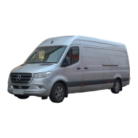
Attachingthe headlashing
&
WARNING Risk of injury due to incor‐
rectly securedloads
When thehooksonthe head lashing are
attached to theringsofthe sliders, theslid‐
erscould come loose. The load maycome
loose, fall down and injurepeople, for
instance when they enter or load and unload
thecargo compartment.
#
Onlyattach thehooksonthe head lash‐
ing to theringsofthe cargo tie-down
rings.
%
The hooks on head lashing 3 mayonlybe
attached to theringsofcargo tie down rings
B.
#
Checkthat theload is seated securely.
#
To attachthe headlashing: tensionhead
lashing 3 at both ends of load 6 and
attachtwo hooks A of thehead lashing to
theringsofcargo tie down rings B.
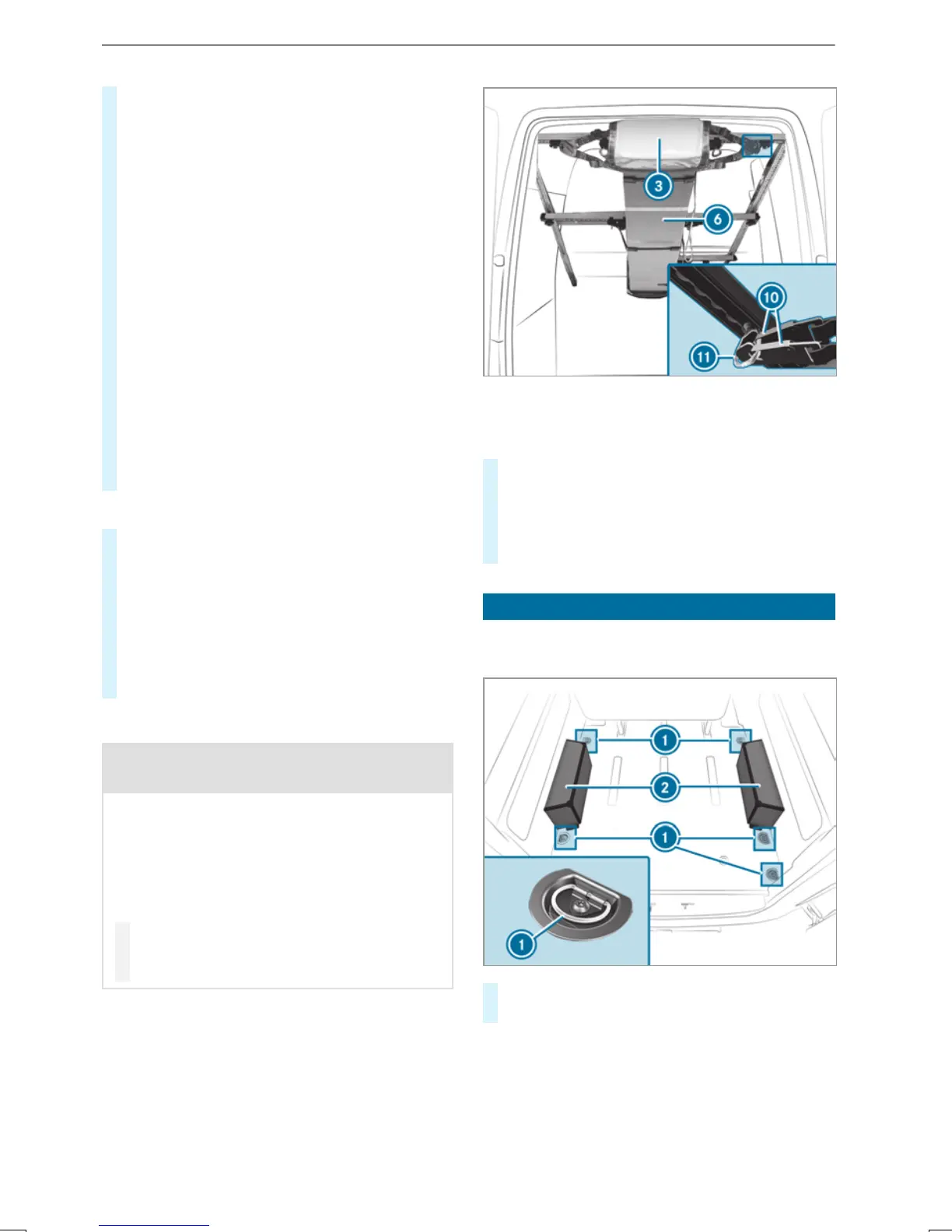
Placing aloadonthe wheel arch
Complywiththe important safety notesunder
"Notesonloading" (/ page73).
#
Place theobjectsonwheel arch 2 and lash
them using tie-down eyes 1(/ page259).
%
Awheel arch maybesubjected to aload of
330lb(150kg).
Transporting
263

 Loading...