6.3 Cables and connectors
6.3.1 Maximum permissible cable lengt
hs
Technical data
Table 6-1 Maximum permissible cable length
Connection type Interface on the converter Maximum permissible cable length (m)
Mains supply X1 (L1, L2, and L3) No restriction
External braking resistor X1 (DCP and R1) 3
24 V DC power supply X124 30
Motor power connection X2 30
Encoder connection X120 30
Motor holding brake X108 30
Control/status inputs and outputs X130 3
PROFINET connection X150 100
Ethernet connection X127 10
STO connection X131 30
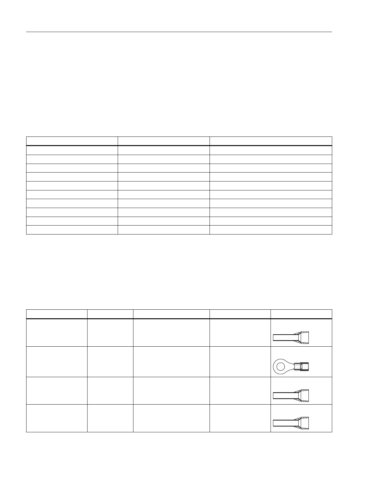
6.3.2 Conductor cross-sections and cable lugs
Description
T
able 6-2 Conductor cross-sections and cable lugs
Connection type Terminal type Conductor cross‑section Stripping length Cable lug
Mains supply (L1, L2,
L3)
Spring-loaded 0.75mm² ... 2.5mm²
(AWG: 14 … 12)
9mm ... 10mm
Pin-type
Mains supply (PE) Screw-type 0.75mm² ... 2.5mm²
(AWG: 14 … 12)
10 mm Ring type
24 V DC power supply Spring-loaded 0.5mm² ... 2.5mm²
(AWG: 20 … 12)
10mm ... 11mm
1)
Pin-type
External braking resis‐
tor
Spring-loaded
0.75mm² ... 2.5mm²
(AWG: 18 … 12)
9mm ... 10mm Pin-type
Connecting
6.3Cables and connectors
SINAMICS S200 PROFINET servo drive system with SIMOTICS S-1FL2
130 Operating Instructions, 11/2023, FW V6.3, A5E51646752B AB

 Loading...


