10.5.3 Torque limit
Overvie
w
The following four sources are available for the torque limit in all control modes. You can select
one of them via a combination of digital input signals TLIM0 and TLIM1 and switch among them
when the converter is running.
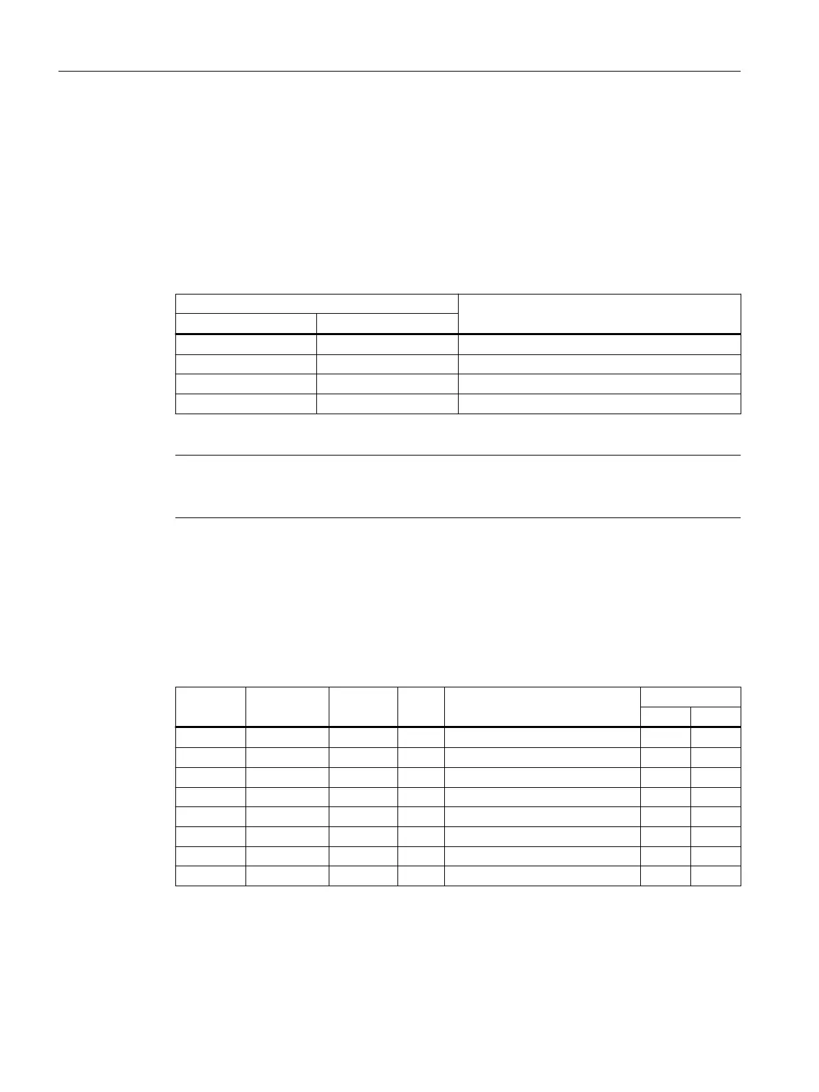
Table 10-13 Combinations of TLIM0 and TLIM1 signals
Digital input Torque limit
TLIM1 TLIM0
0 0 Internal torque limit 0
0 1 Internal torque limit 1
1 0 Internal torque limit 2
1 1 Internal torque limit 3
In addition to the above four sources, the overall torque limit is also valid.
Note
When the
motor torque exceeds the torque limit of the selected group determined by TLM0 and
TLM1, fault F07900 occurs.
Description of function
Internal tor
que limit
Select an internal torque limit by setting the following parameters.
Table 10-14 Parameter - internal torque limit
Parameter Value range Default Unit Description Digital input
TLIM1 TLIM0
p29050[0] -150 ... 350 350 % Internal torque limit 0 (upper) 0 0
p29050[1] -150 ... 350 350 % Internal torque limit 1 (upper) 0 1
p29050[2] -150 ... 350 350 % Internal torque limit 2 (upper) 1 0
p29050[3] -150 ... 350 350 % Internal torque limit 3 (upper) 1 1
p29051[0] -350 ... 150 -350 % Internal torque limit 0 (lower) 0 0
p29051[1] -350 ... 150 -350 % Internal torque limit 1 (lower) 0 1
p29051[2] -350 ... 150 -350 % Internal torque limit 2 (lower) 1 0
p29051[3] -350 ... 150 -350 % Internal torque limit 3 (lower) 1 1
The following diagram shows how the internal torque limit functions. When the torque
setpoint reaches the torque limit, the actual torque output is limited to the value selected by
TLIM0/TLIM1.
Functions
10.5General functions
SINAMICS S200 PROFINET servo drive system with SIMOTICS S-1FL2
360 Operating Instructions, 11/2023, FW V6.3, A5E51646752B AB

 Loading...


