6.5.4.3 Wiring
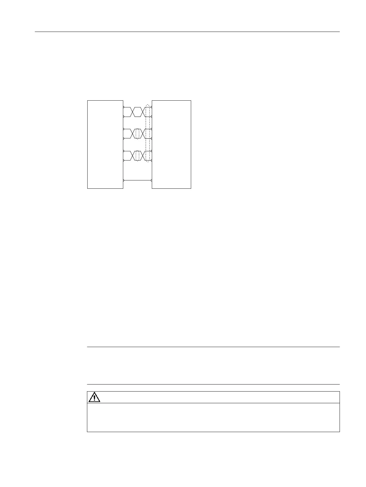
Connection example
<HOORZ
*UHHQ
%URZQ
%OXH
5HG
:KLWH
&RQYHUWHUVLGH
0RWRUVLGH
*URXQGLQJ
6KLHOGLQJ
&ORFNB3
&ORFNB1
'DWDB3
'DWDB1
39
0
0
3B6XSSO\
&ORFNB3
&ORFNB1
'DWDB3
'DWDB1
Figure6-10 Encoder connection
More information
F
or more inf
ormation about cable requirements, see Section "Cables and connectors
(Page130)".
For more information about assembling cable terminals, see Section "Assembling cables
(Page879)".
6.5.5 Rotating the connectors at the motor
Overview
The connectors at the 1FL2 motor with shaft heights 45, 48, 52, 65, and 90 can be rotated to a
dierent angle to a limited extent.
Use a suitable socket connector as a lever to rotate the connector.
Note
Rot
ating the connectors
• Do not exceed the permissible range of rotation.
• To ensure the degree of protection, do not rotate more than 10 times.
WARNING
Adjusting cable directions
Bef
or
e adjus
ting the cables, switch o the power supply. Otherwise, the motor contains a
hazardous voltage and a risk of electric shock.
Connecting
6.5Connecting the motor
SINAMICS S200 PROFINET servo drive system with SIMOTICS S-1FL2
Operating Instructions, 11/2023, FW V6.3, A5E51646752B AB 145

 Loading...


