CYLINDER BLOCK DISASSEMBLY
EG0FB–01
(See page EG–98)
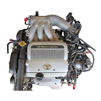
1. REMOVE REAR OIL SEAL RETAINER
Remove the six bolts and retainer.
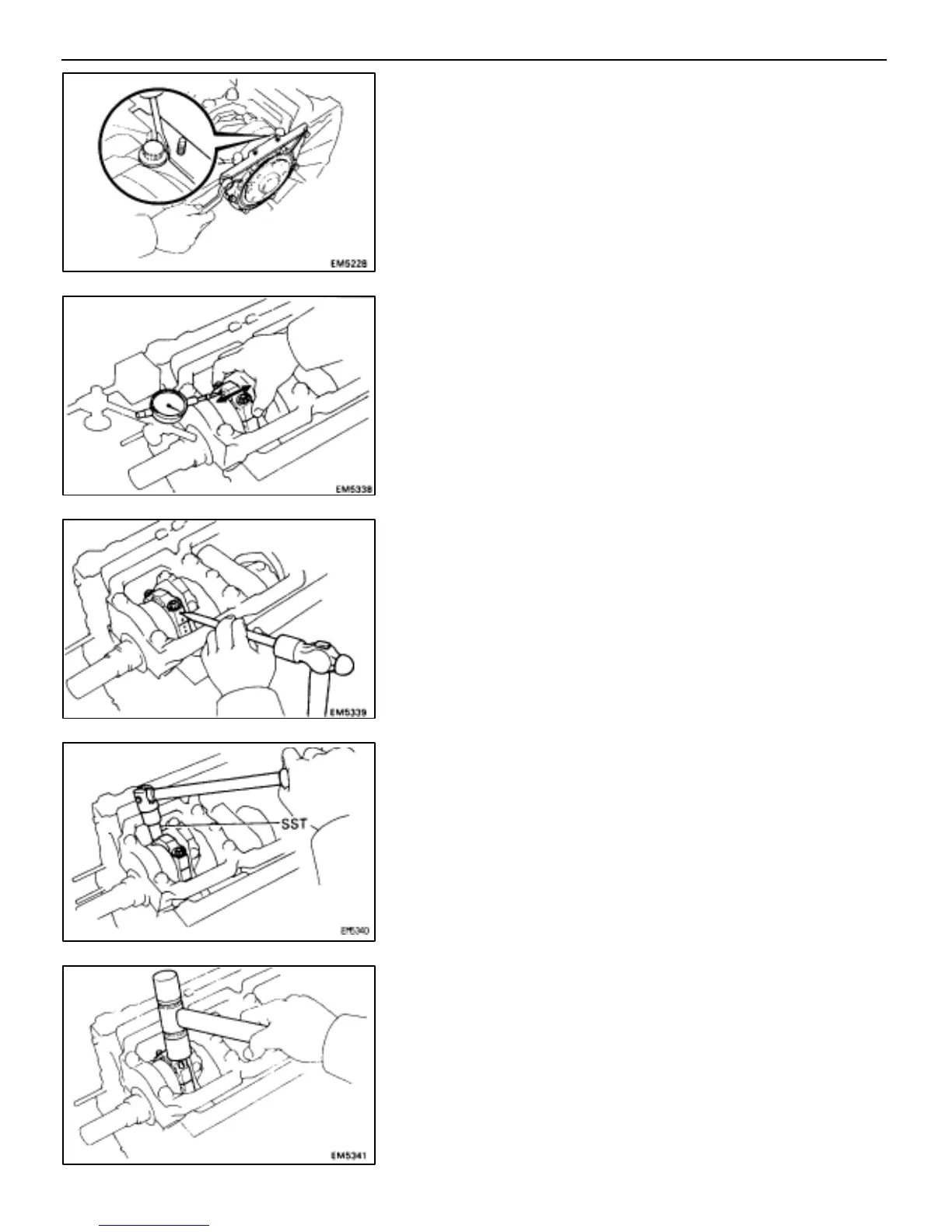
2. CHECK CONNECTING ROD THRUST CLEARANCE
Using a dial indicator, measure the thrust clearance while
moving the connecting rod back and forth.
Standard thrust clearance:
0.150–0.330 mm (0.0059–0.0130 in.)
Maximum thrust clearance:
0.38 mm (0.0150 in.)
If the thrust clearance is greater than maximum, replace the
connecting rod assembly. If necessary, replace the crank-
shaft.
3. REMOVE CONNECTING ROD CAPS AND CHECK OIL
CLEARANCE
(a) Using a punch or numbering stamp, mark the connecting rod
and cap to ensure correct reassembly.
(b) Using SST, remove the connecting rod cap nuts.
SST 09011–38121
(c) Using a plastic–faced hammer, lightly tap the connecting rod
bolts and lift off the connecting rod cap.
HINT: Keep the lower bearing inserted with the connecting
cap.
–ENGINE TROUBLESHOOTING ENGINE MECHANICAL
EG–101
 Loading...


