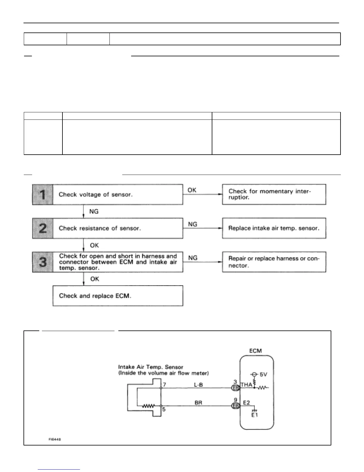
WIRING DIAGRAM
DTC 24 Intake Air Temp. Sensor Circuit
CIRCUIT DESCRIPTION
The intake air temp. sensor is built into the volume air flow meter and senses the intake air temperature.
The structure of the sensor and connection to the ECM is the same as the water temp. sensor shown on page
EG–370.
If the ECM records the diagnostic trouble code “24”, it operates the fail safe function, keeping the intake air tem-
perature at a constant 20C (68F).
Code No. Diagnostic Trouble Code Detecting Condition Trouble Area
24
Open or short in intake air temp. sensor circuit for 0.5
sec. or more.
Open or short in intake air temp. sensor cir-
cuit.
Intake air temp. sensor
ECM
(See page EG–333).
EG–374
–ENGINE TROUBLESHOOTING CIRCUIT INSPECTION

 Loading...