D. Inspect piston pin fit
At 60°C (140°F), you should be able to push the piston pin
into the piston pin hole with your thumb.
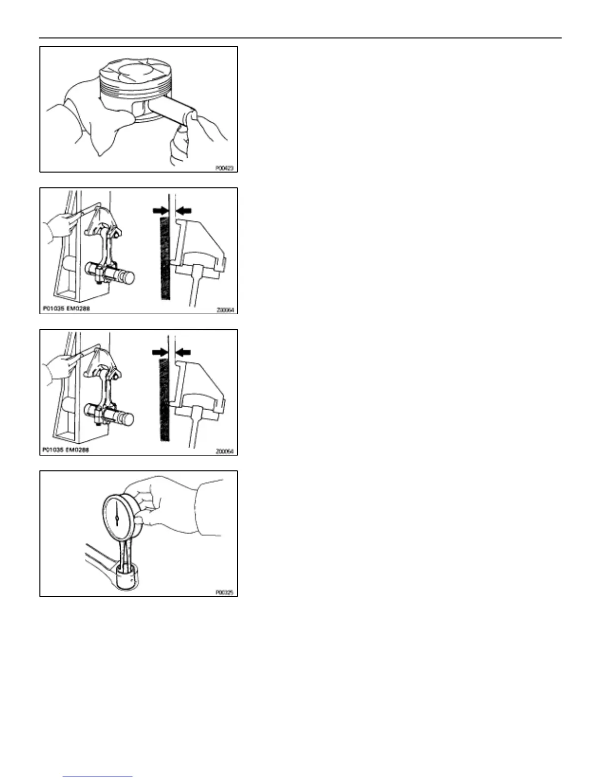
3. INSPECT CONNECTING ROD
A. Inspect connecting rod alignment
Using a rod aligner and thickness gauge, check the connect-
ing rod alignment.
•Check for bend.
Maximum bend:
0.05 mm (0.0020 in.) per 100 mm (3.94 in.)
If bend is greater than maximum, replace the connecting rod
assembly.
•Check for twist.
Maximum twist:
0.15 mm (0.0059 in.) per 100 mm (3.94 in.)
If twist is greater than maximum, replace the connecting rod
assembly.
B. Inspect piston pin oil clearance
(a) Using a caliper gauge, measure the inside diameter of the
connecting rod bushing.
Bushing inside diameter:
22.005–22.014 mm (0.8663–0.8667 in.)
(b) Using a micrometer, measure the piston pin diameter.
Piston pin diameter:
21.997–22.006 mm (0.8660–0.8664 in.)
(c) Subtract the piston pin diameter measurement from the
bushing inside diameter measurement.
Standard oil clearance:
0.005–0.011 mm (0.0002–0.0004 in.)
Maximum oil clearance:
0.05 mm (0.0020 in.)
If the oil clearance is greater than maximum, replace the
bushing. If necessary, replace the piston and piston pin as a
set.
–ENGINE TROUBLESHOOTING ENGINE MECHANICAL
EG–113
 Loading...


