HINT:
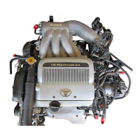
•Keep the bearings, connecting rod and cap together.
•Arrange the piston and connecting rod assemblies in correct
order.
5. CHECK CRANKSHAFT THRUST CLEARANCE
Using a dial indicator, measure the thrust clearance while pry-
ing the crankshaft back and forth with a screwdriver.
Standard thrust clearance:
0.020–0.220 mm (0.0008–0.0087 in.)
Maximum thrust clearance:
0.30 mm (0.0118 in.)
If the thrust clearance is greater than maximum, replace the
thrust washers as a set.
Thrust washer thickness:
2.440–2.490 mm (0.0961–0.0980 in.)
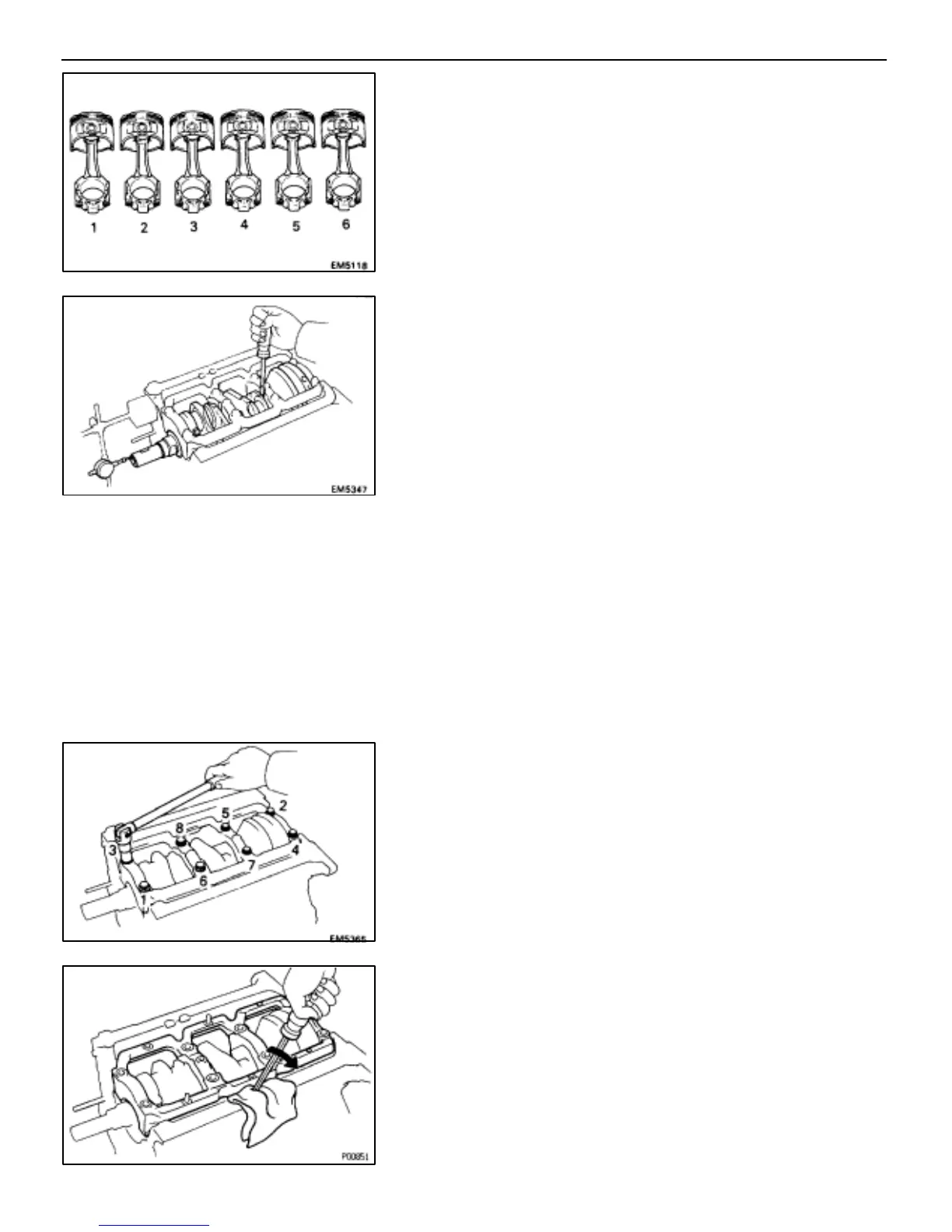
6. REMOVE MAIN BEARING CAP AND CHECK OIL
CLEARANCE
(a) Uniformly loosen and remove the main bearing cap bolts in
several passes, in the sequence shown.
(b) Using a screwdriver, pry up the main bearing cap, and
remove the main bearing cap, lower main bearings and lower
thrust washers (No.2 journal position of main bearing cap
only).
HINT: Keep the lower main bearings and lower thrust wash-
ers together with the main bearing cap.
(c) Lift out the crankshaft.
HINT: Keep the upper main bearings and upper thrust wash-
ers together with the cylinder block.
EG–104
–ENGINE TROUBLESHOOTING ENGINE MECHANICAL
 Loading...


