Fuel System Circuit
CIRCUIT DESCRIPTION
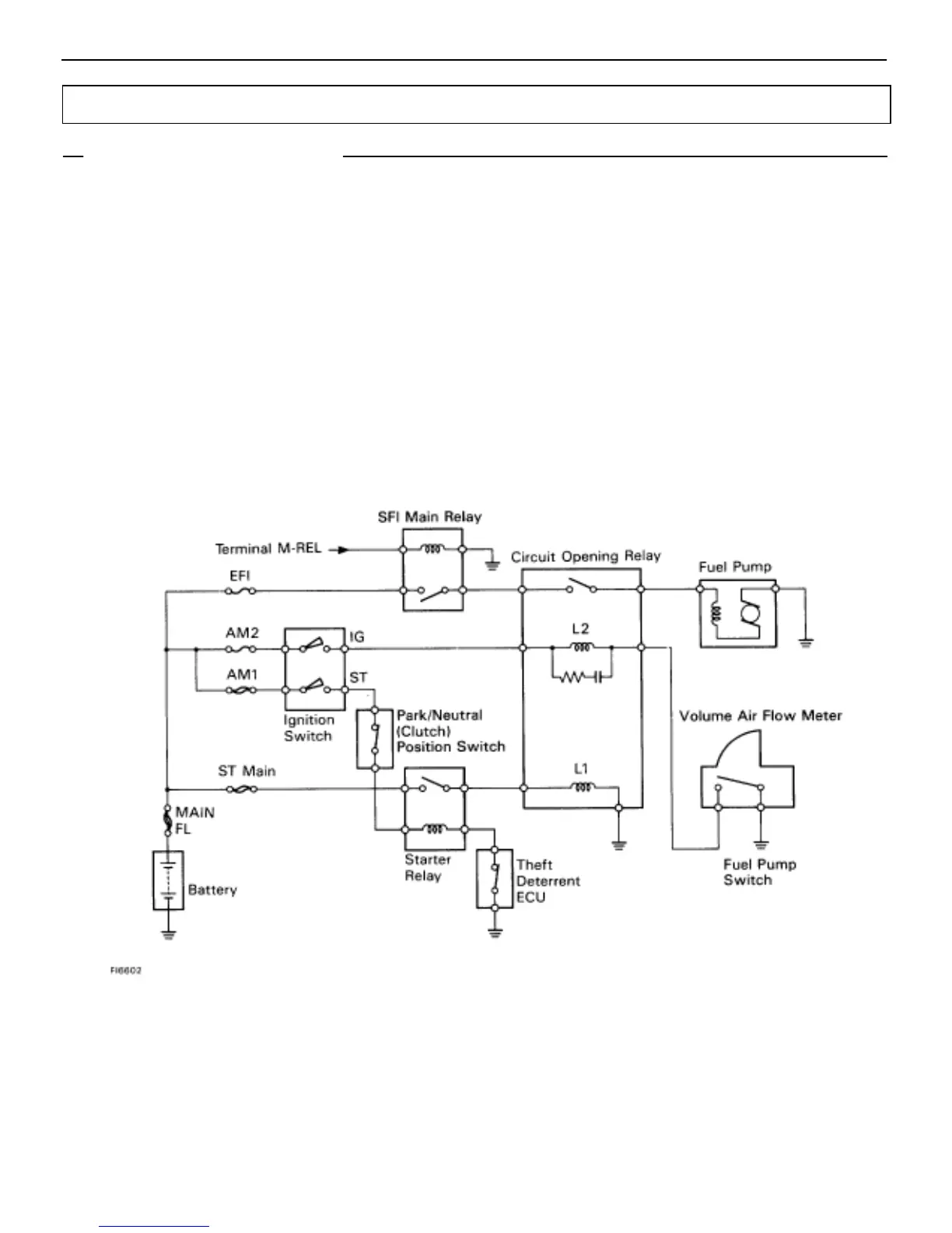
In the diagram below, when the engine is cranked, current flows from terminal ST of the ignition switch to the
starter relay coil, the starter relay switches on and current flows to coil L1 of the circuit opening relay. Thus the
circuit opening relay switches on, power is supplied to the fuel pump and the fuel pump operates. After the en-
gine cranks, the cylinders beginning in air, causing the measuring plate inside the volume air flow meter to open.
This turns on the fuel pump switch, which is connected to the measuring plate, and current flows to the L2 coil
of the circuit opening relay.
After the engine starts and the ignition switch is turned from START back to ON, current flowing to the L1 coil
of the circuit opening relay is cut off. However current continues to flow to the L2 coil even after the engine starts
due to the fuel pump switch inside the volume air flow meter. As a result, the circuit opening relay stays on, allow-
ing the fuel pump to continue operating.
EG–440
–ENGINE TROUBLESHOOTING CIRCUIT INSPECTION
 Loading...


