WIRING DIAGRAM
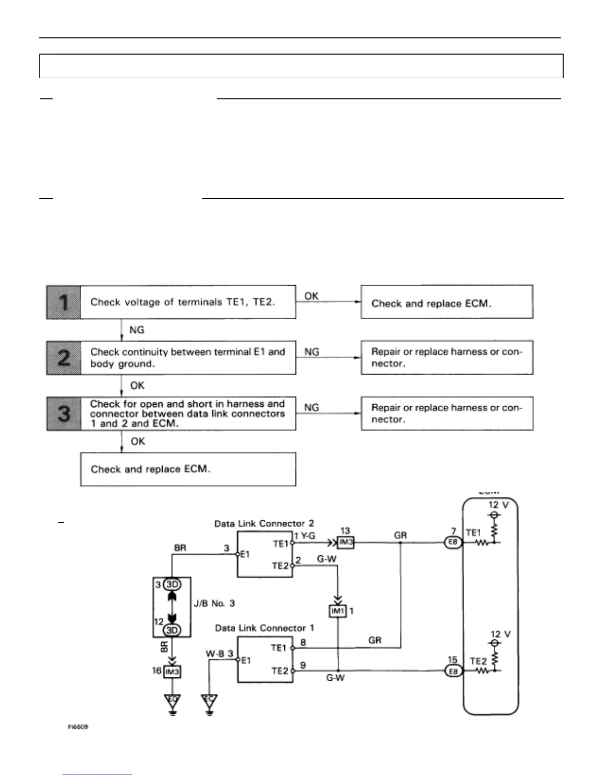
TE1, TE2 Terminal Circuit
CIRCUIT DESCRIPTION
Terminals TE1 and TE2 are located in the data link connectors 1 and 2. The data link connector 1 located in
the engine compartment and the data link connector 2 located in the cabin. When these terminals are connected
with the E1 terminal, diagnostic trouble codes in normal mode or test mode can be read from the Malfunction
Indicator Lamp on the combination meter.
HINT: If terminals TE1 and TE2 are connected with terminal E1, diagnostic trouble code is not output or test
mode is not activated.
Even though terminal TE1 is not connected with terminal E1, the Malfunction Indicator Lamp blinks.
For the above phenomenon, the likely cause is an open or short in the wire harness, or malfunction inside the
ECM.
EG–456
–ENGINE TROUBLESHOOTING CIRCUIT INSPECTION
 Loading...


