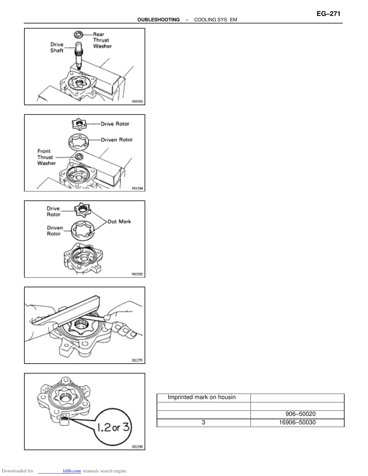
3. REMOVE REAR THRUST WASHER AND DRIVE SHAFT
4. REMOVE DRIVE AND DRIVEN ROTORS
5. REMOVE FRONT THRUST WASHER
HYDRAULIC MOTOR INSPECTION
EG0AG–01
1. INSPECT DRIVE AND DRIVEN ROTORS
(a) Install the drive and driven rotor to the motor housing with the
dot mark facing upward.
(b) Using a thickness gauge and precision straight edge,
measure the side clearance between the rotor and precision
straight edge.
Standard side clearance:
0.01–0.04 mm (0.0004–0.0016 in.)
Maximum side clearance:
0.05 mm (0.0020 in.)
If the clearance is greater than maximum, replace the rotors
as a set. If necessary, replace the motor assembly.
HINT: When replacing the rotors, select the new rotor set ac-
cording to the imprinted mark on the motor housing.
Imprinted mark on housing
Rotor set
1
16906–50010
2
16906–50020
3
16906–50030
–ENGINE TROUBLESHOOTING COOLING SYSTEM
EG–271
 Loading...


