SECTION 4
4-3
NOTE
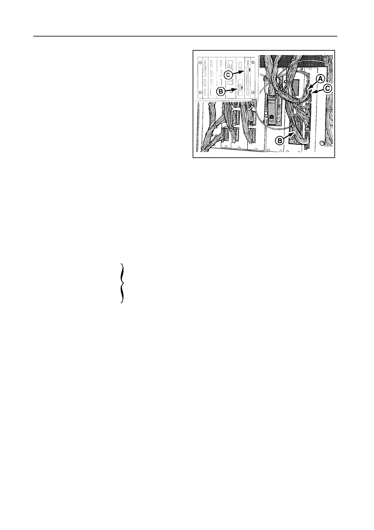
Figure 3:
When using a grain or maize header fitted with
autofloat sensors, plug A must be plugged into
socket B.
When using a flex header, plug A must be
plugged into socket C, as shown.
NOTE:
S The header calibration must be performed
when changing the header.
S To operate a flex header, the autofloat op-
eration mode must be selected.
OPERATION MODES
With the header control selector switch 17 four differ-
ent operation modes are possible:
1 Transport operation = Manual
2 Compensation operation
3 Stubble height operation
4 Autofloat operation
Automatic
header height
controls
=
Transport operation -- Figure 1
ALWAYS use this mode for road transport, attaching
and detaching the header.
When the threshing mechanism is disengaged, this
mode is automatically selected.
T urn selector switch 17 fully counterclockwise and
raise the header by pushing on the upper part of
rocker switch 13 (2-speed function).
Lower the header by pushing on the lower part of
rocker switch 13 (2-speed function).
T ilt down the left-hand side of the header by pushing
on the left part of button 13.
T ilt down the right-hand side of the header by pushing
on the right part of button 13.
51714
3
 Loading...