OPERATION
2-6
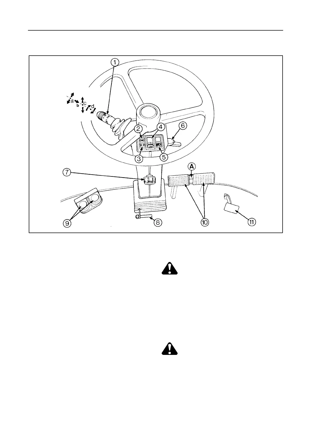
STEERING COLUMN AND CONTROL PEDALS -- Figure 6
6
42764
1 - a Direction indicator lever (linked up with
buzzer)
- b Push button for horn
- c Headlights selector switch
- d Parking and dipped headlights switch and all
outside 12-Volt DC plugs (portable light)
2 Direction indicator warning light
3 Header trailer direction indicator warning light
(linked up with buzzer)
4 Hazard warning lights switch (linked up with
buzzer)
5 Headlights control indication
6 Steering wheel tilt control (clamping screw)
7 Steering wheel height control (clamping
screw)
8 Steering column tilt control (push pedal)
CAUTION:
Adjust the steering wheel only when the
combine is stopped.
9 Reel fore and aft adjustment
- Right-hand pedal: forwards
- Left-hand pedal: rearwards
10 Foot brake pedals with pedal coupler A
CAUTION:
For safety reasons, always couple brake
pedals by means of pedal coupler A when
driving on public roads. This ensures the
brakes are actuated together.
11 Differential lock pedal [if installed]
 Loading...