ADJUSTMENTS AND MAINTENANCE
5-56
ELECTRICAL SYSTEM
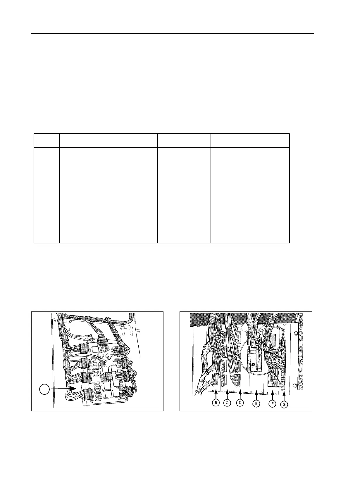
FUSES AND RELAYS -- Figures 99 and 100
All fuses and relays are situated in the box above the
right-hand traction wheel, except for the start relay
and the 12 - 24 V transformer (for these parts, refer to
the Service Parts Catalogue).
Item Description Connectors Relays Fuses
A Power module X31 - X39 K1 - K10 F1 - F37
B CPU monitor X44 - X46 -- --
(Central process unit)
C Remote control printed circuit X49 - X52 K32 - K48 --
D Relay module X53 - X56 K21 - K31 --
E Header compensation X57 -- --
control module
F Lateral float and (ultrasonic) X58 - X59A -- --
autofloat module
G Flex header reel speed printed X59B - X65 -- --
circuit
SUMMARY -- Figures 99 and 100
IMPORTANT:
1. When replacing a fuse, make sure the
new fuse has the same ampere rating
as the fuse being replaced.
2. When replacing a relay, make sure the
new relay has the same ampere rating
and the same structure (visible on the
relay housing).
Always use genuine parts.
30231
99
51714
100
A

 Loading...