FIELD OPERATION
4-10
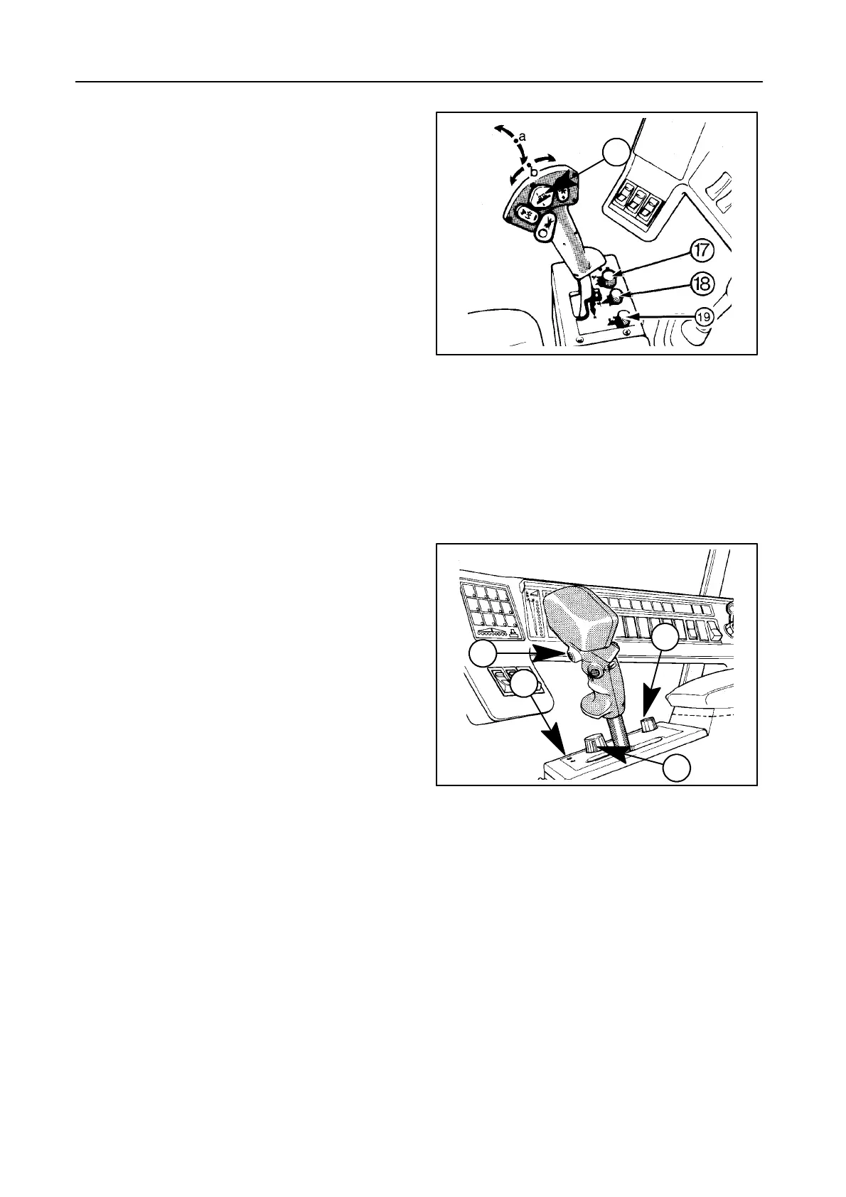
Calibration of the ground level through autofloat
sensors -- Figures 10 and 11
NOTE:
S Ensure the autofloat sensors are con-
nected.
S If a flex header is installed, perform this
calibration only during calibration of the In-
foView Monitor. Refer to paragraph headed
‘‘InfoView monitor’’, subheading 1.6, fur-
ther in this Section.
1. Loosen the plastic fixation strips holding the outer
header skids and ensure the skids are in pivoting
postion (i.e. hanging loose) [not applicable for flex
header].
2. Start the engine.
3. Select the transport position with selector switch
17.
4. Lower and lift the header with the header height
control rocker switch 13 at least once.
5. Lower the header onto the ground with the header
height control rocker switch 13 and ensure the
header rests flat onto the ground. If not, adjust the
inclination with rocker switch 13.
6. Check if the autofloat sensors are operating (a
buzzing noise is audible at the sensors) [not appli-
cable for flex header].
7. Push the automatic header height switch 20 and
simultaneously lift the header slowly (1st speed)
with header height control rocker switch 13.
Hold both switches (even with the header in the
highest position) until the green autodiagnostic in-
dicator 22 has blinked 10 times.
8. Secure the plastic fixation strips of the header
skids [not applicable for flex header].
43073
10
11
13
42972
20
22
17
19
 Loading...