CHAPTER 4 LASER EXPOSURE SYSTEM
COPYRIGHT
©
2002 CANON INC. 2000 CANON iR1600/iR2000 REV.1 JAN. 2002
4-8
4 Controlling the Scanner Motor
4.1 Outline
The following are items of control related to the scanner motor:
[1] scanner motor constant speed rotation
[2] scanner pre-rotation control
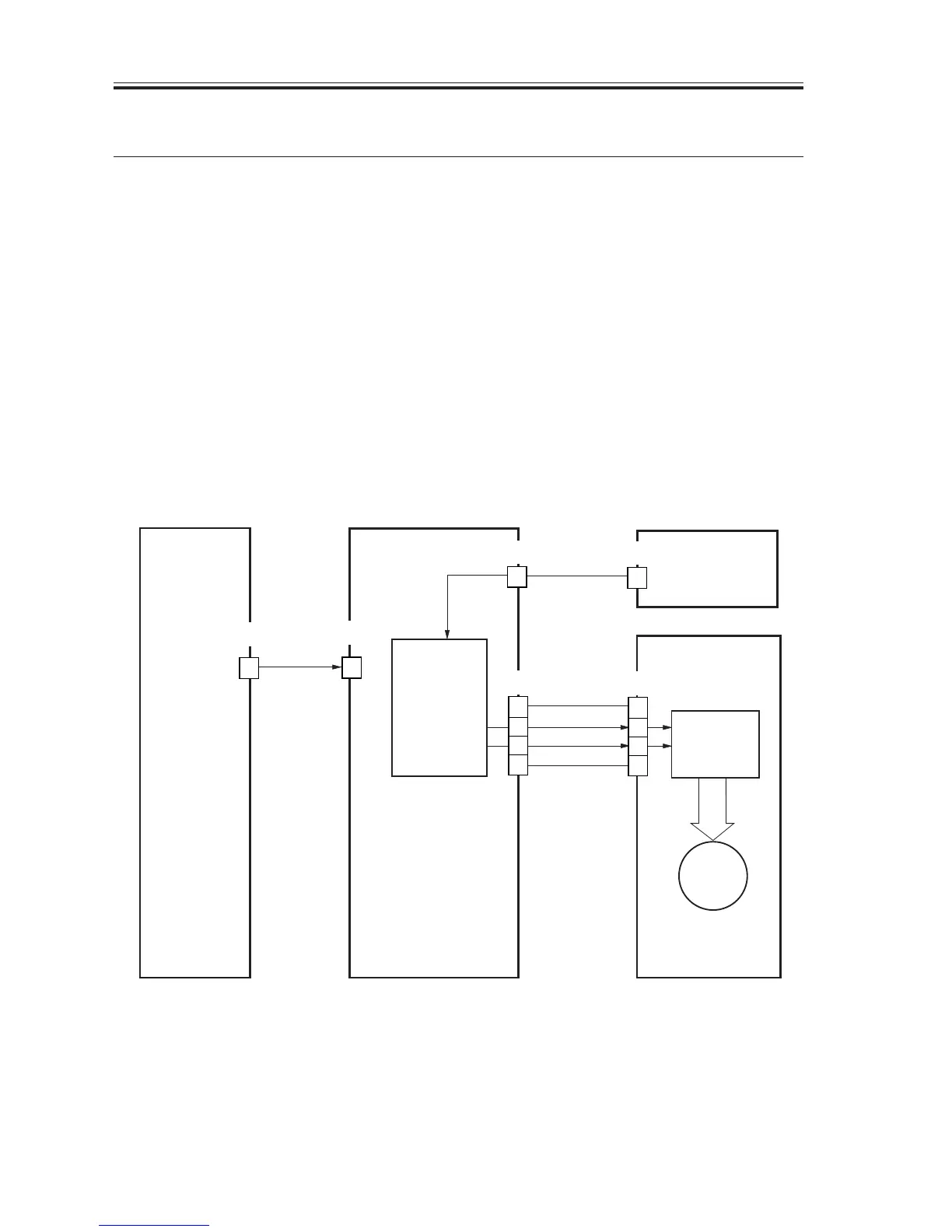
4.2 Controlling the Scanner Motor
The scanner motor is controlled as follows:
[1] When the print signal goes ‘0’, printing is started or continued.
[2] When the scanner motor acceleration signal goes ‘0’, the scanner motor goes ON.
[3] The BD input signal goes ‘0’ when laser light is detected.
[4] The cycle of the BD input signal and the target cycle are compared, and the result is
used to control the scanner motor.
[5] When the scanner motor deceleration signal goes ‘0’, the scanner motor goes off.
F03-402-01
M102
[1]PRNT*
[3]BDIN*
+24V
[2]ACCO*
[5]DECO*
GND
[4]
12
13
14
15
J102
4
3
2
1
J911
10
J102
2
J908
14
J106
14
J235
Image
processor
PCB
DC controller
PCB
Comparison
circuit
Laser
scanner motor
BD PCB
Drive circuit

 Loading...


