CHAPTER 2 BASIC OPERATION
COPYRIGHT
©
2002 CANON INC. 2000 CANON iR1600/iR2000 REV.1 JAN. 2002
2-6
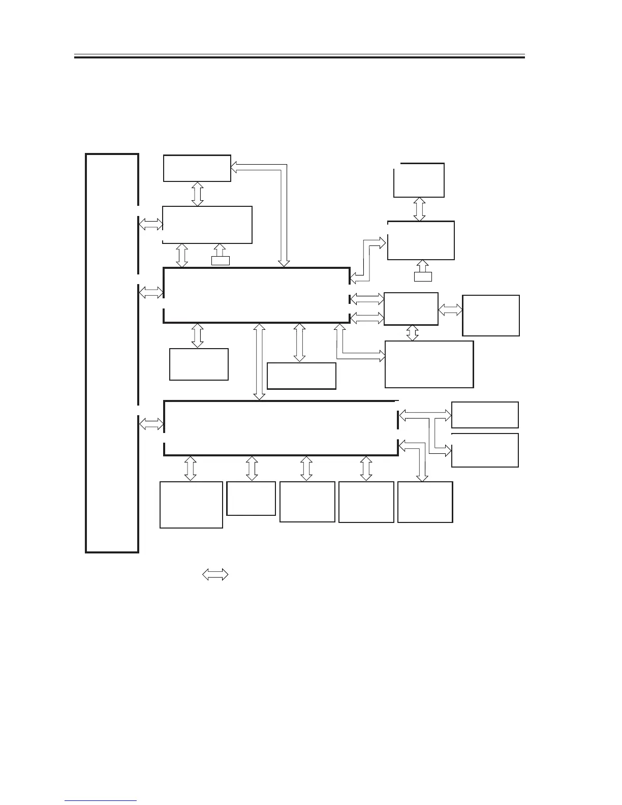
1.3 Inputs to and Outputs from Electrical Components
1.3.1 Wiring Diagram of the Major PCBs
F02-103-01
J11
J263
J15
J210
J1131
J2
J21
CN2
J105
J102
CN3
J907
J12
CN1
J201
J1
A
J901
/903
J264
J112
J1
J109
J1
J101
J5
J101
J1501
J1501
J101
J908
J3
J930
J1
J235
J104
J209
J212
J6
J234 J5
J203
J221
J2
A
Power supply
PCB
ADF (accessory)
Original detection/
reader motor drive PCB
Image processor PCB
Card reader
(accessory)
Control panel PCB
DC controller PCB
CS unit
Analog processor
PCB
Printer board
(accessory)*1
Hard disk drive
(accessory)
Network interface board
(accessory)*1
Laser unit
BD detection PCB
Inner 2-way tray
(accessory)
Finisher
(accessory)
1-cassette unit
(accessory)
2-cassette unit
(accessory)
3-cassette unit
(accessory)
*1: standard if printer model.
Note: The symbol in the diagram indicates a major connection, not the nature of a signal

 Loading...


