CHAPTER 8 EXTERNALS AND AUXILIARY CONTROL SYSTEM
COPYRIGHT
©
2002 CANON INC. 2000 CANON iR1600/iR2000 REV.1 JAN. 2002
8-24
6.5 PCBs
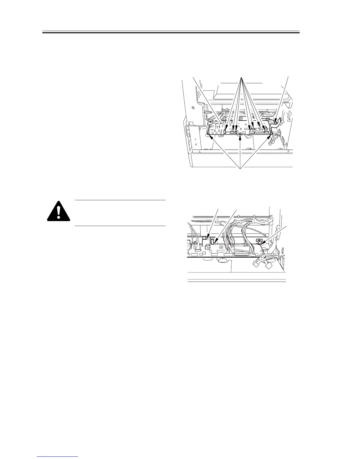
6.5.1 Removing the DC Controller PCB
1) Remove the power supply PCB. (6.5.9
in Chapter8)
2) Disconnect all connectors [1] and the
flexible cable [2] from the DC control-
ler PCB.
3) Remove the 3 screws [3], and detach the
DC controller PCB [4].
F08-605-01
When mounting the PCB, be
sure that the 3 high-voltage con-
tacts [5] are as indicated.
4) If you have replaced the PCB, go
through the instructions given for re-
placement (See to 2.3.5 in Chapter 13).
F08-605-02
6.5.2 After Replacing the DC Controller PCB
1) After replacing the PCB, go through the
steps given under 2.1.3 of Chapter 13 to
adjust the leading edge margin and to
check if the image leading edge margin
is as indicated.
2) If not, perform the steps so that the mar-
gin is as indicated.
[4] [1] [2]
[3]
[5]
[5]
[5]

 Loading...


