COPYRIGHT
©
2002 CANON INC. 2000 CANON iR1600/iR2000 REV.1 JAN. 2002
6-12
CHAPTER 6 PICKUP/FEDING SYSTEM
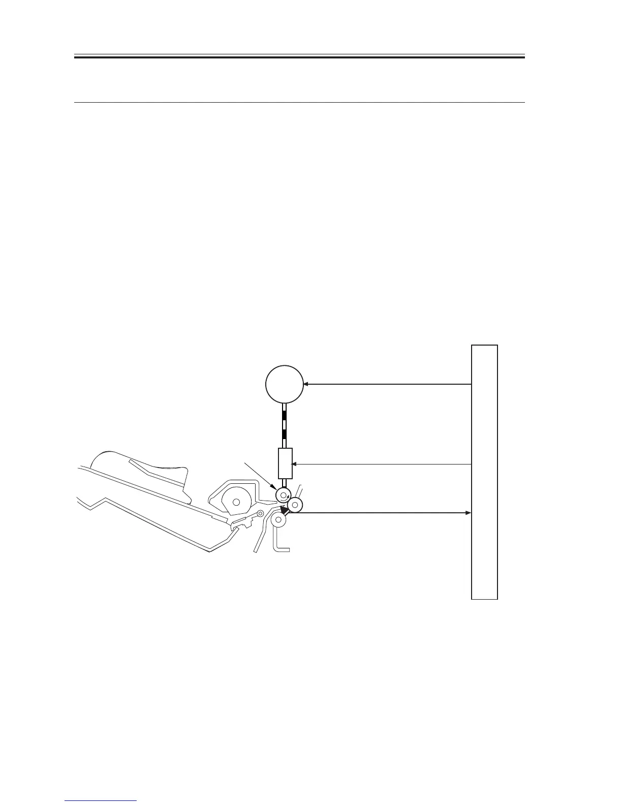
3 Controlling the Registration Roller
3.1 Detecting the Leading Edge of Paper
The paper coming from the pickup assembly is moved farther to the transfer assembly
when the registration clutch (CL101) goes ON and the registration roller starts to rotate as a
result.
The DC controller PCB sends the vertical sync signal (TOP*) to the image processor PCB
when the registration paper sensor (PS101) detects the leading edge of paper.
A specific period of time after the image processor PCB receives the TOP* signal, video
signals (VDO*, VDO) are sent so that the leading edge of the image on the photosensitive
drum and the leading edge of paper will match. The paper is then moved through the trans-
fer, separation, and fixing assemblies to reach the delivery tray.
The original leading edge margin adjustment volume (VR101) mounted on the DC con-
troller PCB may be used to change the timing at which the registration clutch (CL101) goes
ON, thereby increasing or decreasing the leading edge margin to suit the original.
F06-301-01
(RGSNS*)
CL101
M101
PS101
(MTRON)
(RGDRV)
Main motor drive signal
Registration clutch drive signal
Registration paper detection
drive signal
DC controller PCB
Registration roller

 Loading...


