CHAPTER 2 BASIC OPERATION
COPYRIGHT
©
2002 CANON INC. 2000 CANON iR1600/iR2000 REV.1 JAN. 2002
2-13
1.5 Controlling the Main Motor (M101)
1.5.1 Outline
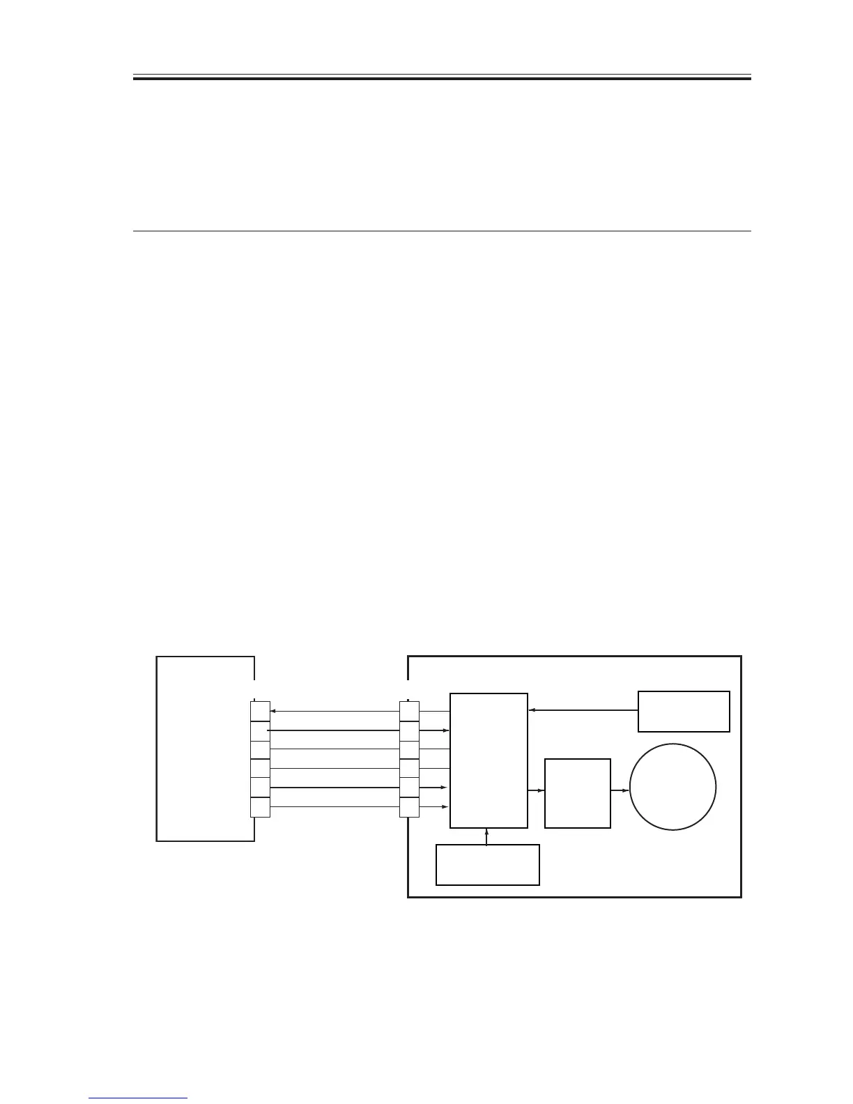
The following table shows the functions of the main motor control circuit, while the fol-
lowing mechanism diagram shows the construction of the circuit:
Item
Power supply
Drive signal
Operation mechanism/
drive mechanism
Control
Error detection
Description
24 V supplied from DC controller PCB
MTRON from DC controller PCB
Registration roller
Multifeeder pickup assembly
Cassette pickup assembly
1-cassette unit pickup assembly
Fixing roller drive assembly
Image formation roller drive assembly
ON/OFF control
Constant speed control
‘E010’
T02-105-01
[1] When the main motor drive signal (MTRON) goes ‘1’, the main motor starts to rotate.
[2] When the main motor has started to rotate and reached a specific revolution, the motor
causes the main motor rotation detection signal (MLOK*) to go ‘0’. If the DC controller
PCB detects an error in the rotation detection signal, it will indicate ‘E010’ in the con-
trol panel.
F02-105-01
J903
3
4
5
6
9
8
7
6
5
4
GND
GND
MTRON
MLOK*
+24VS
+24VR
J106
2
1
DC controller
PCB
Drive control
circuit
Reference signal
generation
Driver
circuit
Rotation speed
detection
Main motor

 Loading...


