CHAPTER 13 TROUBLESHOOTING
COPYRIGHT
©
2002 CANON INC. 2000 CANON iR1600/iR2000 REV.1 JAN. 2002
13-11
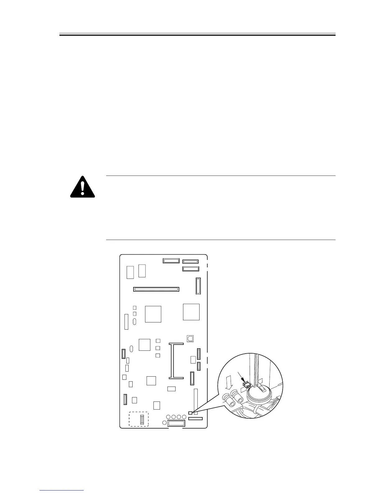
2.3.4 When Replacing the Image Processor PCB
a.Before Starting the Work
1) Generate a counter report by making the following selections in service mode: #10
REPORT>COUNTER REPORT.
The couther report provides a user data list, changes made to the default settings of the
system data list, and system dump list (not used).
2) Turn off the power switch, and disconnect the jumper plug (JP201) from the existing
PCB.
3) If an expansion memory has been mounted, remove the memory from the image proces-
sor PCB.
4) Remove the ROM DIMM.
5) Remove the screw, and detach the counter PCB [1].
When the jumper plug (JP201) is removed, all data stored in the control
memory will be lost. Be sure to check that the control data has been printed
before removing the plug.
The data in the control memory includes the following:
user data : data set by the user by pressing the Additional function key in
the control panel.
service mode data : service mode settings data
F13-203-01
J204
BAT1
JP201
J271
J216
J204
J221
J264
J209
J211
J212
J263
J208
J206
JP201
[1]

 Loading...


