COPYRIGHT
©
2002 CANON INC. 2000 CANON iR1600/iR2000 REV.1 JAN. 2002
6-4
CHAPTER 6 PICKUP/FEDING SYSTEM
2.1.2 Pickup form the Cassette
The rotation of the pickup roller is controlled by the pickup roller drive gear used to trans-
mit the drive of the main motor (M101) to the gear of the pickup drive shaft and the cassette
pickup solenoid (SL101).
When the main motor rotates, the drive relay gear starts to rotate in response. At this time,
the area of the pickup roller gear without a tooth is located at the relay gear; the absence of
engagement between both gears prevents the drive from reaching the pickup roller shaft.
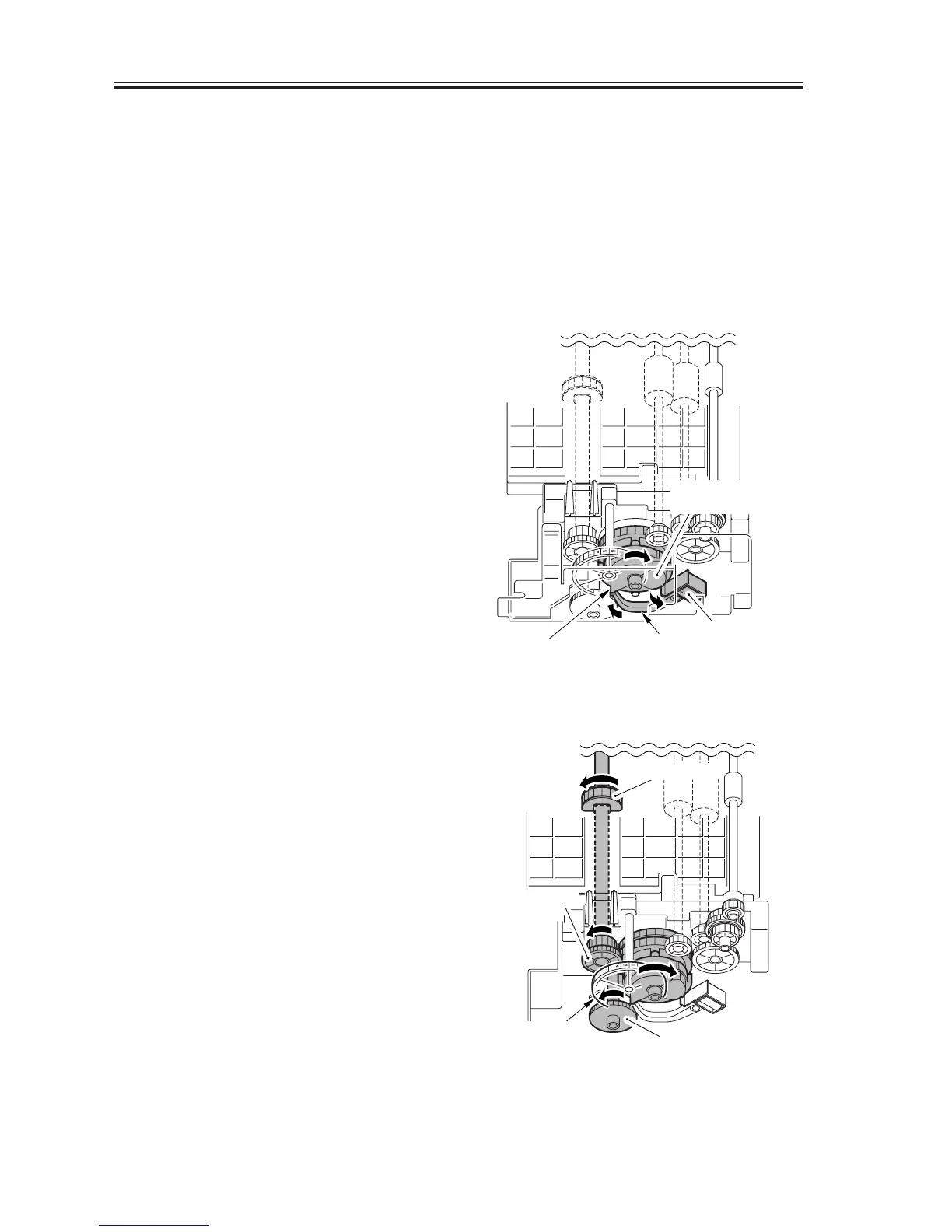
1. The DC controller PCB generates the
cassette pickup solenoid drive signal
(CSTFD) to turn on the solenoid; as a
result, the control arm pushes the cam
to rotate the pickup roller drive gear
slightly.
F06-201-02
2. When the pickup roller drive gear and
the pickup roller shaft gear engage, the
drive reaches the pickup roller shaft
gear to rotate the pickup roller.
F06-201-03
Cam
Arm
Solenoid
Pickup roller
drive gear
Pickup roller
Pickup roller
shaft gear
Drive relay gear
Relay gear

 Loading...


