CHAPTER 3 IMAGE READING/PROCESSING SYSTEM
COPYRIGHT
©
2002 CANON INC. 2000 CANON iR1600/iR2000 REV.1 JAN. 2002
3-8
4 Image Processing
4.1 Outline
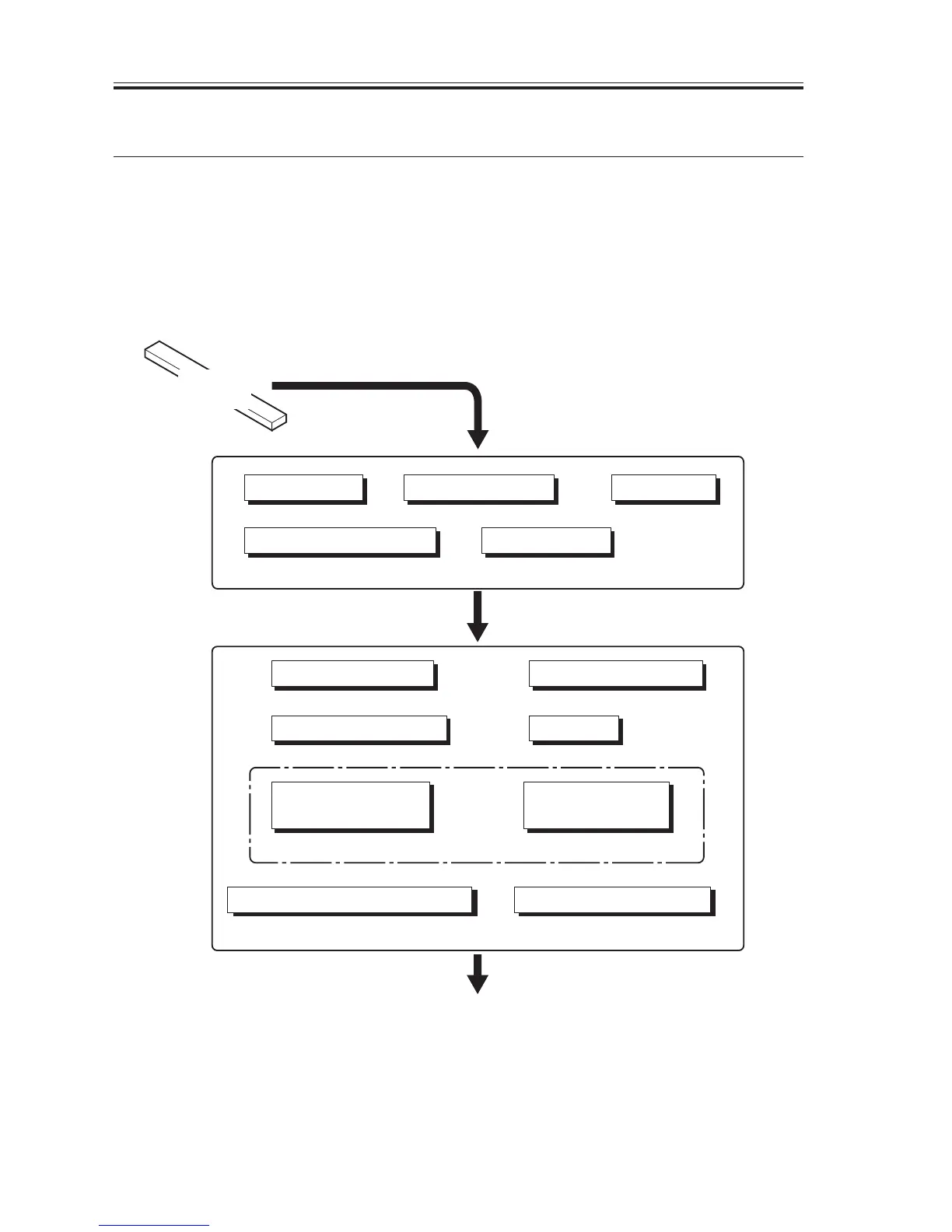
The machine performs image processing and correction in copier mode as shown in the
following block diagram.
The image data (analog signals) read by the contact sensor is converted into digital signals
by the analog processor PCB. The resulting image data is subjected to processing/correction
by the analog processor PCB and image processor PCB.
F03-401-01
(OS1 to 4)
Contact
sensor
Analog image data
A/D conversion
LED intensity processing
Shading correction
ABC processing
Analog processor PCB
Re-ordering
8-bit digital image data
Binary error diffusion
edge emphasis/editing
density adjustment
(F-value conversion)
Compression/expansion/rotation
To printer control block
Image processor PCB
Image memory (SDRAM)
Density conversion (LUT)
Smoothing
Enlargement/reduction
Density correction
(γ conversion)

 Loading...


