Fig. 3-3 1022 – Explanation of the symbols (part 3)
- 1022 -
Function diagram
87654321
fp_1022_51_eng.vsd
DO: All objects
SINAMICS
17.07.13 V04.07.00
Explanations on the function diagrams - Explanation of the symbols (part 3)
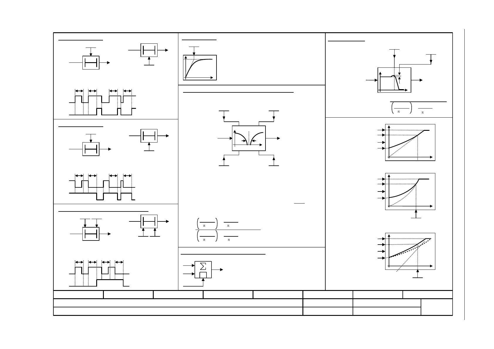
Switch-on delay
T0
xy
pxxxx
The digital signal x must have the value "1" without any interruption
during the time T before output y changes to "1".
PT1 element
PT2 low pass
0T
Switch-off delay
xy
pxxxx
The digital signal x must have the value "0" without interruption during
the time T before output y changes to "0".
Delay (switch-on and switch-off)
T
1
T
2
T0
pxxxx
0T
pxxxx
xy
xy
The digital signal x must have the value "1" without interruption during
time T
1
or must have the value "0" during time T
2
before output y
changes its signal state.
xy
T
1
T
2
xy
pxxxx pxxxx
pxxxx pxxxx
x
TT TT
y
TT
x
y
x
TT
y
T
1
T
1
T
2
T
2
yx
H(s) =
s
2
fn_n 2 fn_n
s + 1
+
+
s
2
fn_d 2 fn_d
2 D_d
2
2
t
y
pxxxx
y
x
1
I
x
2
1
yx
f
|y|
fn
D
Mot U_rated p0304
U_output max r0071
Linear
p0310
Parabolic
U_output max r0071
p0310
Mot U_rated p0304
H(s) =
+
s
2
fn_d
2 fn_d
2 D_d
2
Flux current control (FCC)
Dependent on the load current
Mot U_rated p0304
U_output max r0071
Mot f_rated
p0310
f_set
f_set
f_set
U_boost total r1315
U_boost total r1315
U_boost total r1315
Analog adder can be activated
The following applies to I = 1 signal: y = x
1
+ x
2
The following applies to I = 0 signal: y = x
1
Delay element, first order.
pxxxx = time constant
Natural frequency, numerator
fn_n
pxxxx
Damping, numerator
D_n
pxxxx
Natural frequency, denominator
fn_d
pxxxx
Damping, denominator
D_d
pxxxx
Used as bandstop filter
- center frequency fs: fn_n = fs
fn_d = fs
- bandwidth f_B: D_n = 0
D_d =
f_B
2 fs
Transfer function when used as general filter
Transfer function
2nd-order filter (bandstop/general filter)
Natural frequency, denominator
fn_d
pxxxx
Damping, denominator
D_d
pxxxx
|y|
f
2nd Order Filter
fs
f_B
2 D_n
s + 1
s + 1