SINAMICS G130/G150
List Manual (LH2), 04/2014, A5E03263479A
27
2 Parameters
2.1 Overview of parameters
Parameter values
22_2 m/s
2
% ft/s
2
% p2007
23_1 Vrms s/m Vrms s/m Vrms s/ft Vrms s/ft -
24_1 Ns/m Ns/m lbf s/ft lbf s/ft -
24_2 Ns/m % lbf s/ft % p2003/p2000
26_1 m/s
3
m/s
3
ft/s
3
ft/s
3
-
39_1 1/s
2
%1/s
2
% p2007
49_1 Nm/rad % lbf ft/rad % p2003
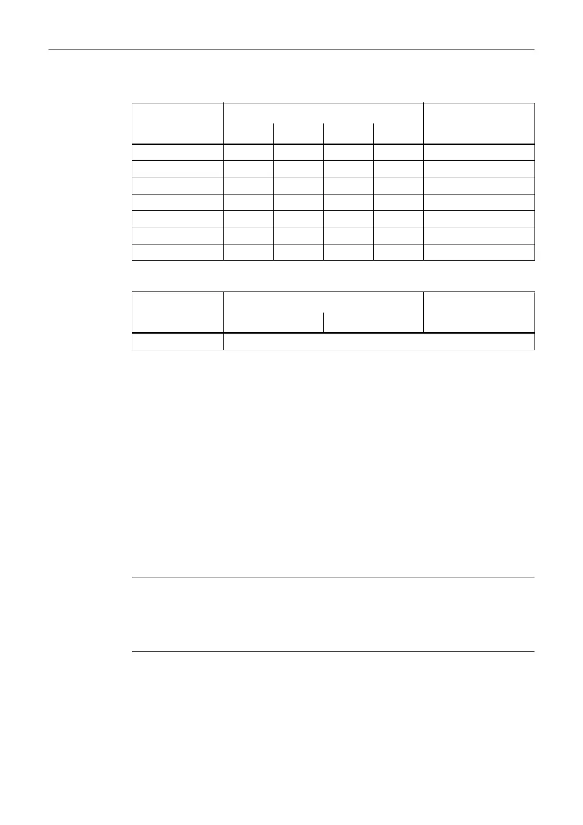
Table 2-6 Unit group (p0595)
Unit group Unit selection for p0595 = Reference variable for %
Value Unit
9_1 The values that can be set and the technological units are shown in p0595.
Table 2-5 Unit groups (p0505), continued
Unit group Unit selection for p0505 = Reference variable for %
1234
Min Minimum value of the parameter [unit]
Max Maximum value of the parameter [unit]
Factory setting Value when delivered [unit]
In the case of a binector/connector input, the signal source of the
default BICO interconnection is specified. A non-indexed
connector output is assigned the index [0].
A different value may be displayed for certain parameters
(e.g. p1800) at the initial commissioning stage or when establishing
the factory settings.
Reason:
The setting of these parameters is determined by the operating
environment of the Control Unit (e.g. depending on converter type,
macro, power unit).
Note
For SINAMICS G130/G150, the macros and their settings are provided in the following
documentation:
References: /BAx/ x = 1, 2
SINAMICS G150/G130 Operating Instructions

 Loading...


