ENGINE
II.
Remove
aff
Plastigage material from the
camshaft and thc bearing caps.
12.
If the oil clcarance
is
grcater than specified
in
Table
1.
and the camshaft bearing journal
dimcnsions are within specifica
ti
on
in
Camsllaft
In
spection. rcplace the cylinder head and
cy
linder
head cover
as
a set.
13.
Remove the camshaft from thc cylinder head.
®
®
@'
(.
I
-l
-
,
,-
•
, -
--
- - -
-
•
,
I
i)
f
..,a
•
t'
, (
~
•
--'
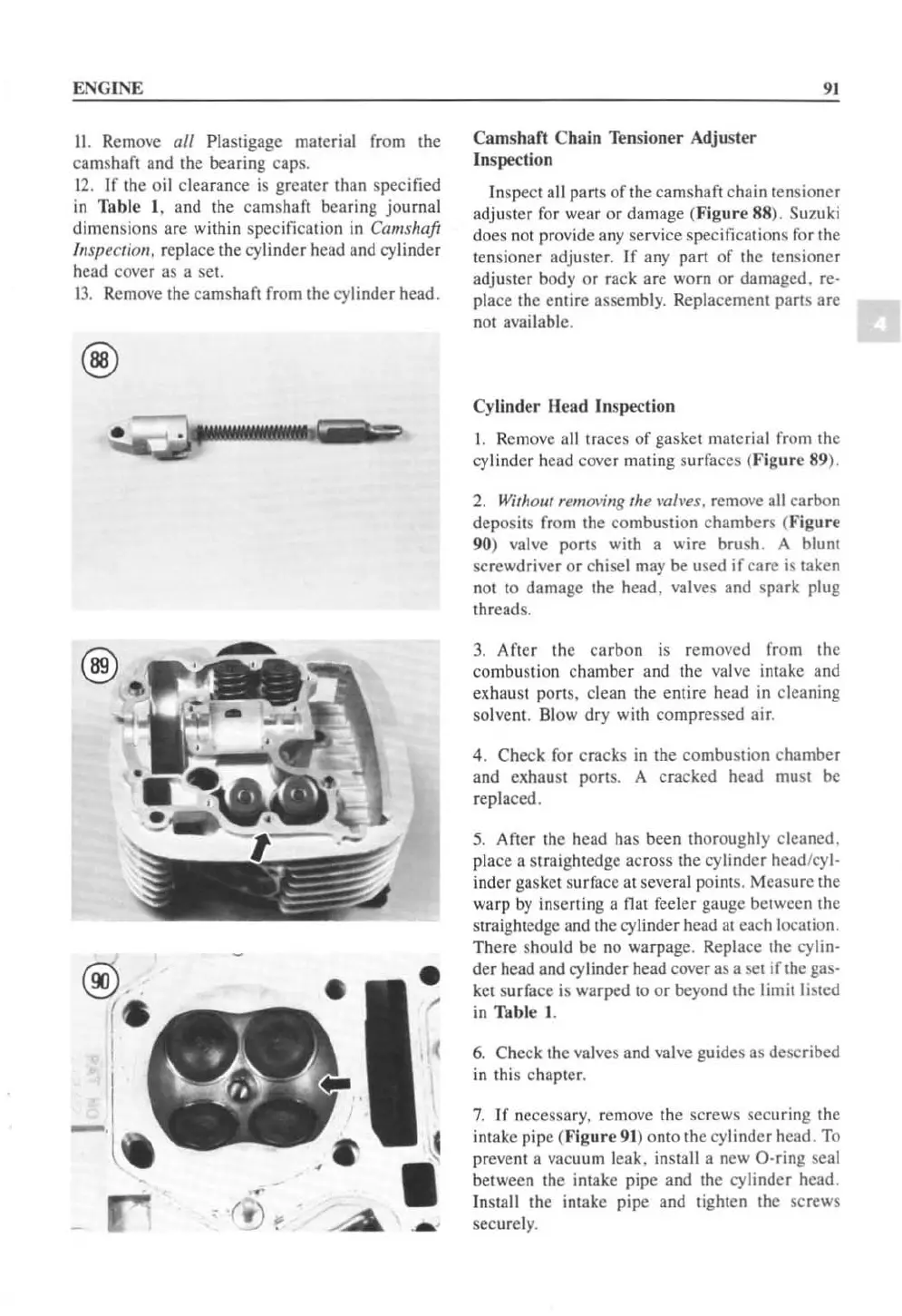
Camsha
ft
Chain Tensioner Adjuster
In
spection
91
In
spect all parts
of
the camshafl chain lensioncr
adjuster
for
wear
or
damage (Figure 88). Suzuki
does not provide
any
scrvice specifications
for
thc
tensioncr adjuster. If any part
of
the tensioner
adjuster body or rack are worn
or
damaged. rc-
place the entire assembly. Replacement parts arc
not availablc.
Cylinder Head
In
spection
I.
Rcmove all traces
of
gasket material from the
cylinder head cover mating surfaces
(F
igure 89).
2.
Witllom remol'illg the mh'es, remove all carbon
deposits from the combustion chambers (Figure
90)
va
l
ve
ports with a wire brush. A blunt
screwdriver or chisel
may
be used if care is taken
not
to
damage the head, valves and spark plug
th
reads.
3.
After the carbon is removed from the
combustion chamber and the valve intake and
exhaust
pOris.
clean the entire head
in
cleaning
so
lvent. Blow dry with comprcssed air,
4. Check
for
cracks in the combustion chamber
and exhaust ports. A cracked head
mu
st
be
rep
la
ced,
5.
After the head has been thoroughly cleaned.
place a straig
ht
edge across the cylinder head/cyl-
inder gasket surface at several points. Measure the
warp
by
inserting a nat feeler gauge between the
st
raightedge and the
cyl
inder head at each location.
There should
be
no warpage. Replace the cylin-
der head and
cy
li
nder head cover as a set if the gas-
ket
su
rface is warped
to
or
beyond the limit
li
sted
in
Table
I.
6.
Check the valves and valve guides
as
described
in
this chapter,
7.
If
necessary. remove the
sc
rews securing the
intake pipe
(F
igure
91
) onto the cylinder head. To
prevent a vacuum leak. install a new
O-ring seal
between the intake pipe and the cylinder head.
In
stall the intake pipe and tighten the screws
securel
y,
 Loading...


