ELECTRICAL SYSTEM
co
nn
eclOr (
Figure
81
) plus the 2 individual wires
(I
li
ght green and I black). One additional wire
fo
r the horn (dark green)
is
attached to the horn:
disconneci
il from the horn.
NaTE
I
II
the/allowing tests. connect the
It'St
leads
10
/he left-hand combirllllion
switch shle
of
the electrical connector.
4.
To lest the headlight
dimmer
switch (
Figure
82). per
fo
rm the following:
a. Usc an ohmmeter and check for continuity.
b.
Turn the headlight dimmer sw
it
ch
to
t
he
HI
position: there should be co
nt
i
nu
ity (low
resistance) between the ye
ll
ow
and the
yellow/white wires.
c. Turn the
headlight
dimmer
sw
it
ch to the LO
pos
il
ion: there should
be
continuity (low
resis
tance
) between the white and the
yellow/white blue wires.
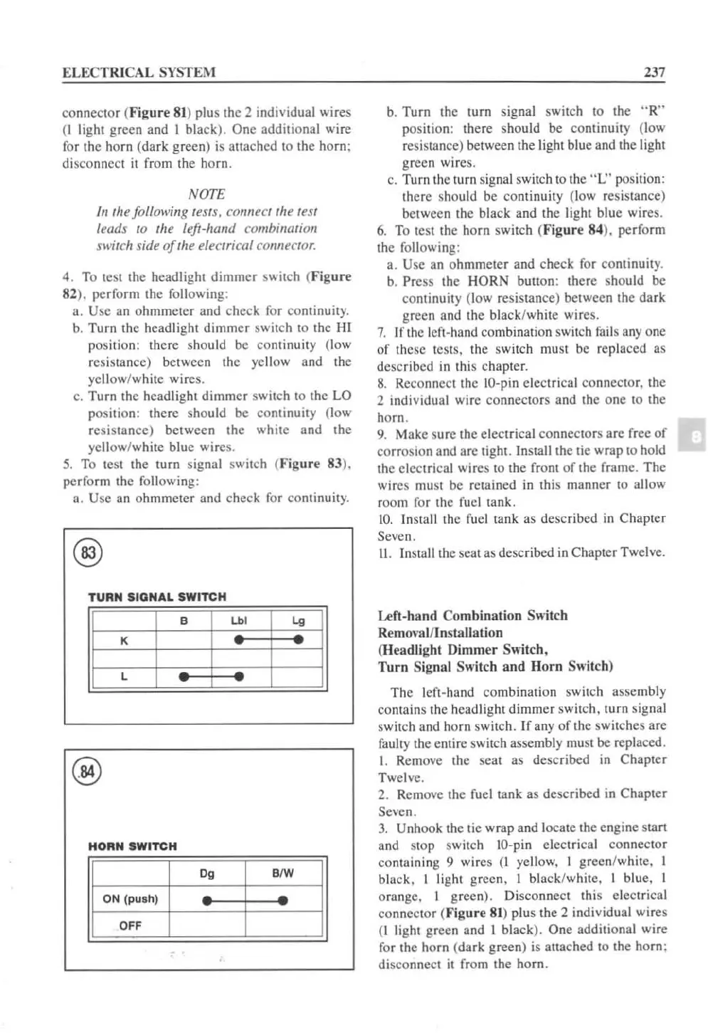
5.
To lest the turn sign
al
sw
it
ch (
Figure
83).
perform the following:
a. Use an ohmmeter a
nd
check for conti
nu
it
y.
@
TURN SIGNAL SWITCH
@
HORN SWITCH
Og
BIW
ON
(p
ush)
OFF
237
b.
Turn the turn signal switch to the " R"
position: there should be continuity (low
resistance) between the
light blue and the light
green wires.
c. Turn
th
e turn signal switch to
th
e " L" position:
there should be continuity
(l
ow resistance)
between the black and the light blue wires.
6.
To test the horn switch (
Figure
84), perform
the
fo
ll
owing:
a.
Use an ohmmeter and check f
or
continu
ity.
b. Pr
ess
the HORN button: there sho
ul
d be
continuity (low resistance) between the
dark
green and the black/white wire
s.
7.
If the left-ha
nd
combination switch
fail
s
anyone
of these tests. the switch must be replaced as
descr
ib
ed in thi s chapte
r.
8.
Re
co
nn
ect the
10
-p
in
ele
ctric
al
co
nnector, the
2 i
nd
ividu
al
wire
co
nnec
tor
s and the one to the
horn.
9. Make sure the electrical co
nn
ectors are free
of
corrosion and arc tight . Install
th
e tie wrap to hold
the electrical wires to the front of the frame. The
wires must be retained
in
th
is
manner to a
ll
ow
room for the fuel tank.
10
.
In
stall the fuel tank as described
in
Chapter
Seven.
II.
Insta
ll
the seat as described
in
Chapter Twelve.
Left-ha
nd
C
ombination
Switch
Removal/Installation
(Headlight
Dimmer
Switch,
Turn
Signal
Sw
itch a
nd
Horn
Switch)
The l
ef
t-hand combination switch assembly
contains the headlight
dimmer
switch, turn signal
switch and h
orn
switch. If any of the switches are
faulty the entire switch assembly
mu
st
be
replaced.
I. Remove the seal as described
in
Chapter
Twel
ve.
2. Remove the fuel tank as
desc
ri
bed in Chapter
Seven.
3.
Unhook the
ti
e wrap and locate the engine start
and stop switch
IO
-pin electrical
co
nn
ect
or
containing 9 wires
(1
yellow. I green/white, I
black, I light green, I black/wh
it
e, I blue. I
orange, I green). Disco
nn
ect this electrical
co
nnector (
Figure
81
) plus the 2 indi
vi
dual wi res
(I light green and 1 black).
One
additional wire
for the horn (
dark
green) is attached to the horn;
disconnect it from the horn.
 Loading...


