288
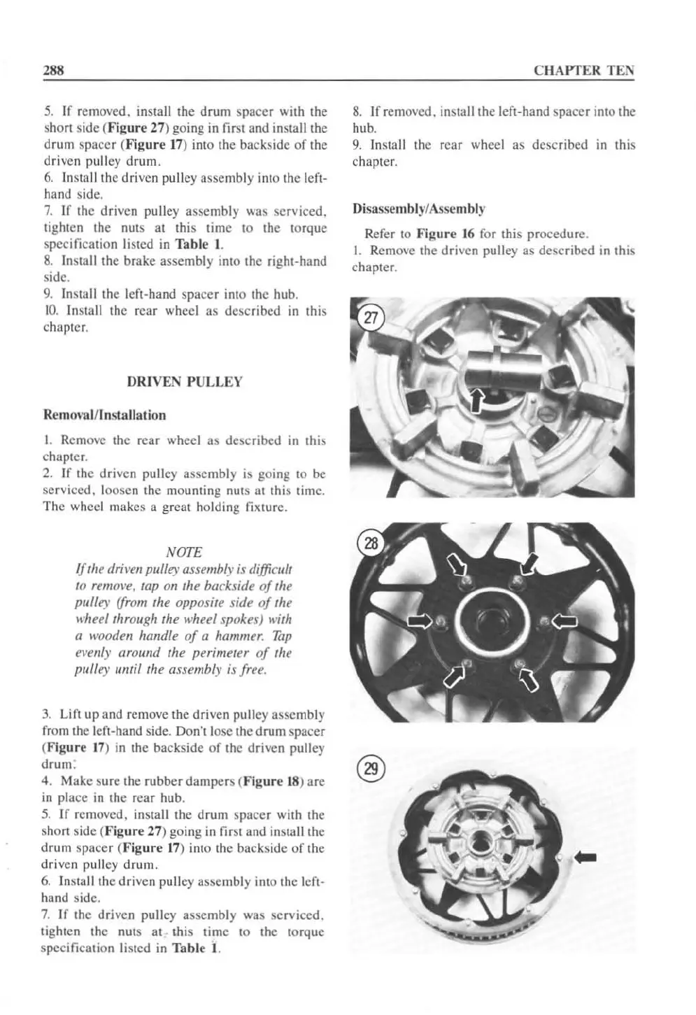
5.
If removed, install the drum spacer with the
sho
rt
side (
Figure
27) going
in
first and install the
drum
spacer (
Figure
17
) into the backside
of
the
driven pulley
drum.
6.
In
stall the driven pulley assembly into the Icfl-
hand side.
7.
If
the driven pu
ll
ey assembly
wa
s serviced.
tighten the
nUls
at this lime to the torque
specification listed in
Tab
le
I.
8.
I
nS
lall the brake assembly into the right-hand
side.
9.
Install the left-hand spacer into the hub.
1
0.
Install the r
ear
wheel as described
in
this
chapter.
DRIVEN P
ULLEY
Remo\
'ul/l
nsta
ll
at
ion
I. Remove the rear wheel as described in this
chapter.
2.
If
the driven pu lley assembly is going to
be
serviced. loosen the mounting
nutS
at
this time.
The wheel makes a great holding
fixture.
N(7TE
IJ
'he driven pulley assembly is difficull
10
remove, lap on
Ihe
backside oJ the
pulley
fJro",
the opposite side
oj
the
wheel through the wheel spokes)
lI';th
a wooden handle
oj
a hammer.
Tap
el'elily around the perimeter
oj
the
{Julley
1IT11i/fhe
assembly is Jree.
CHAPTER TEN
8.
If removed. install the left-hand
spacer
into the
hub.
9.
Install the rear wheel as dcscribcd
in
this
chapter.
Disassem blyl Asse
mbl
y
Rcfer to
Figure
16 for this procedure.
\. Removc the drivcn pulley as described in this
chapter.
3.
U
ft
up
and remove the driven pulley asscmbly
from the left-hand side.
Don'tlosc
the drum spacer
(
Figure
17)
in
the backsidc
of
thc driven pulley
drum:
f'29\
4. Make sure the rubber dampers (
Figure
18
)
;:are
\.!::)
in
pl;:ace
in the rear hub.
5.
If
removed, install the drum
spacer
with the
short side
(F
ig
ur
e 27) going
in
first and insta
ll
the
drum spa
cer
(
Figure
17
) into the backside
of
the
dr
iven pulley drum.
6.
insta
ll
the driven pu
ll
ey assembly into the left-
hand side.
7.
If the driven pulley assembly was service
d.
tighten the nuts
at
~
this time to the torque
specification listed
in
Table
I.
 Loading...


