ENGINE
Piston Ring Replacement
WARNING
Th
e edges
of
all
pistol! rings are very
sha
rp
.
Be
careflll when handling them
to
avoid cutting fingers.
1.
Measure the
si
de clearance
of
each ring in its
groove
with a flat feeler gauge (
Figure
117
) and
compare to dimensions given
in
Table
1.
If the
clearance
is
greater than specified. the rings must
U5
be
replaced.
If
the clearance is still excessive with
the new rings. the piston must also
be
replaced.
2. Remove the old
lOp
ring
by
spread
in
g the ends
with your thumbs just enough to slide the ring up
over
th
e
pi
s
ton
(
Figur
e
178
).
Repeal for the
remaining rings.
3.
Carefully remove all carbon buildup from the
ring grooves
with a broken piston ring (Figure
179
). Inspecllhe grooves carefully for burrs. nicks
or broken and cracked lands.
Re
co
ndition
or
replace the piston if necessar
y.
4.
Roll
each ring around
its
piston groove as shown
in
Figure
180
to check
fo
r binding. Minor binding
may
be cleaned up with a fine·cut file.
5.
Measure the thickness of each ring with a
micrometer and compare to dimensions given
in
Table
I.
If
the thickness is less than specified. the
ring(s)
mu
st be replaced.
6.
First. measure the free end gap of each ring with
a
ve
rnier caliper and compare to dimensions given
in
Table I. If the end cap
is
greater than specified.
the ring(s) must be replaced.
7.
Aft
er
measuring the free end gap. place each
ring. one at a time. into the cylinder and push
it
in
about 20 mm
(3/4
in.) with the crown
of
the
piston to ensure that the ring is square
in
the
cy
linder bore. Measure the gap with a nat feeler
gauge and compare to dimensions
in
Table
I.
If
the gap is greater than specified. the rings should
be replaced.
8.
When installing new rings. measure their end
gap as described
in
Step 6 and Step 7 and compare
to dimensions given in Table
I.
If the end cap
is
greater than specified, rewrn the rings for another
set.
NOTE
lr/Sfall the
2nd
and
lOp
ring \\'itll its
"T"
mark facing
up.
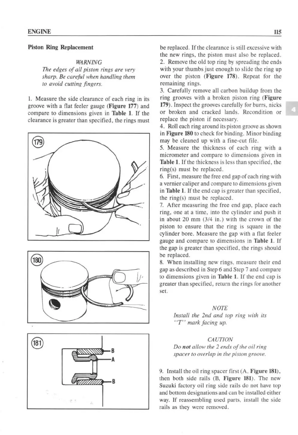
CAUTION
Do
not allow the 2 ends
of
the
oil
ring
spacer
to
ol'erlap
in
the
pistOlI
grool'e.
9.
In
sta
ll
the
oi
l ring spacer lir
st
(A.
Figure
18
1).
then both s
id
e rai ls (B
.•
'
igure
181
). The ncw
Suzuki factory oil ring side rails do not havc top
and bottom designations and can
be installed cither
way.
If reassembling used parts.
in
stall the side
rails as they
wc
re removed.
 Loading...


