144
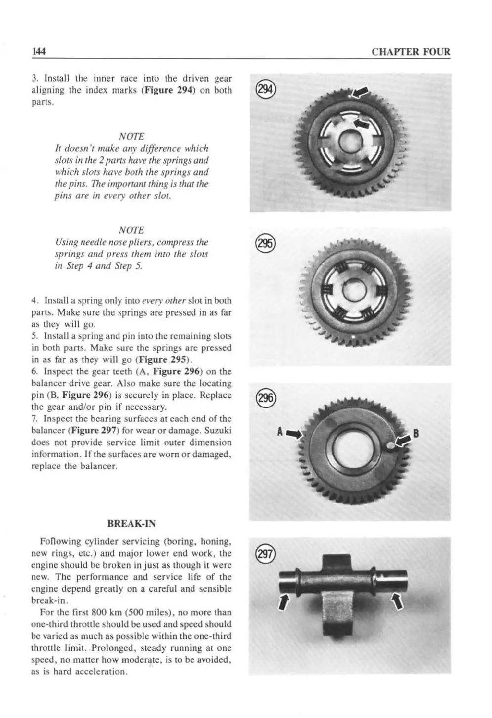
3.
In
stall the inner race into the driven gcar
aligning the
index marks (
Figore
294) on both
parts.
NOTE
II
(Joes"
"
make
an>,
difference which
SIOIS
in
the 2 pllrts h(H't
Ihe
springs (111(/
which slots hal'l!
both
the springs arid
the
pins.
The
importartllhing is th
at
the
pins
are in el'ery other slot.
NOTE
Using needle /lose pliers. compress the
springs and press them into the slots
in
Step 4
mid
Step
5.
4.
In
sta
ll
a spring only into e'I'ery
orhu
sl
ot
in
both
parts. Make sure the springs atc pressed
in
as far
as they wi
ll
go.
5.
Inslall a spring and pin into the remaining slots
in
both
pans
. Make sure the
sp
rings
arc
pressed
in
as
far
as
they will go (.' igure 295
),
6. Inspect the
gear
teeth (A.
Figure
296
) on the
balanc
er
drive
gear. Also make sure the locating
pin
(8.
Figure
296
)
is
securely
in
place. Replace
the gear and/
or
pin if necessary.
7.
Inspect the bearing surfaces at each end
of
the
balancer (
Figure
297
) for wear
or
damage. Suzuki
does not provide service limit
outer
dimension
information.
If
the surfaces are worn
or
damaged.
replace the balancer.
BREAK-IN
Fonowing cylinder servicing (boring, honing.
new rings. etc.) and
major
lower
end
work,
the @
engine should be broken in
just
as though it were
new.
The
performance and service life
of
the
engine depend greatly on a careful and sensible
break·in.
For the first
800
km (500 miles), no more than
one-third throttle should
be
used and speed should
be
va
ried as much as possible within the one-third
throttle limit.
Prolonged. steady running at one
speed. no matter how moderate, is to
be
avoided.
as is hard acceleralion.
CHAPTER FOUR
A
 Loading...


