ENG
I
NE
Va
h'e Seat Reconditioning
Special valve cutter lools
and considerable
ex
pertise are required
10
prope
rl
y recondition the
valve seats
in
the
cy
linder head.
You
can save
con
si
der
ab
le money
by
removing the
cyli
nder head
a
nd
taking just the
cy
linder head
to
a dealer or
ma
chine shop and ha
ve
the val
ve
seatS
ground.
The
fo
llowing procedure
is
provided if
you
choose
10
perform this
ta
sk
yoursel
f.
The Suzuki valve scat cu
tt
er
and T-handle are
available
fr
om a Suzuki dealer or from
ma
chine
shop supply outlets. Foll
ow
the manu
fa
c
tu
rer's
instruction
in
regard to operating
th
e cutter.
You
will
ne
ed
th
e Suzuki
Valv
e Scat Cutter (N-1l6
),
a
T-handle and the Sol
id
Pilot
(N-
1OO-6
.98)
or
equi
va
lent.
Vat
ve
seat
10
5
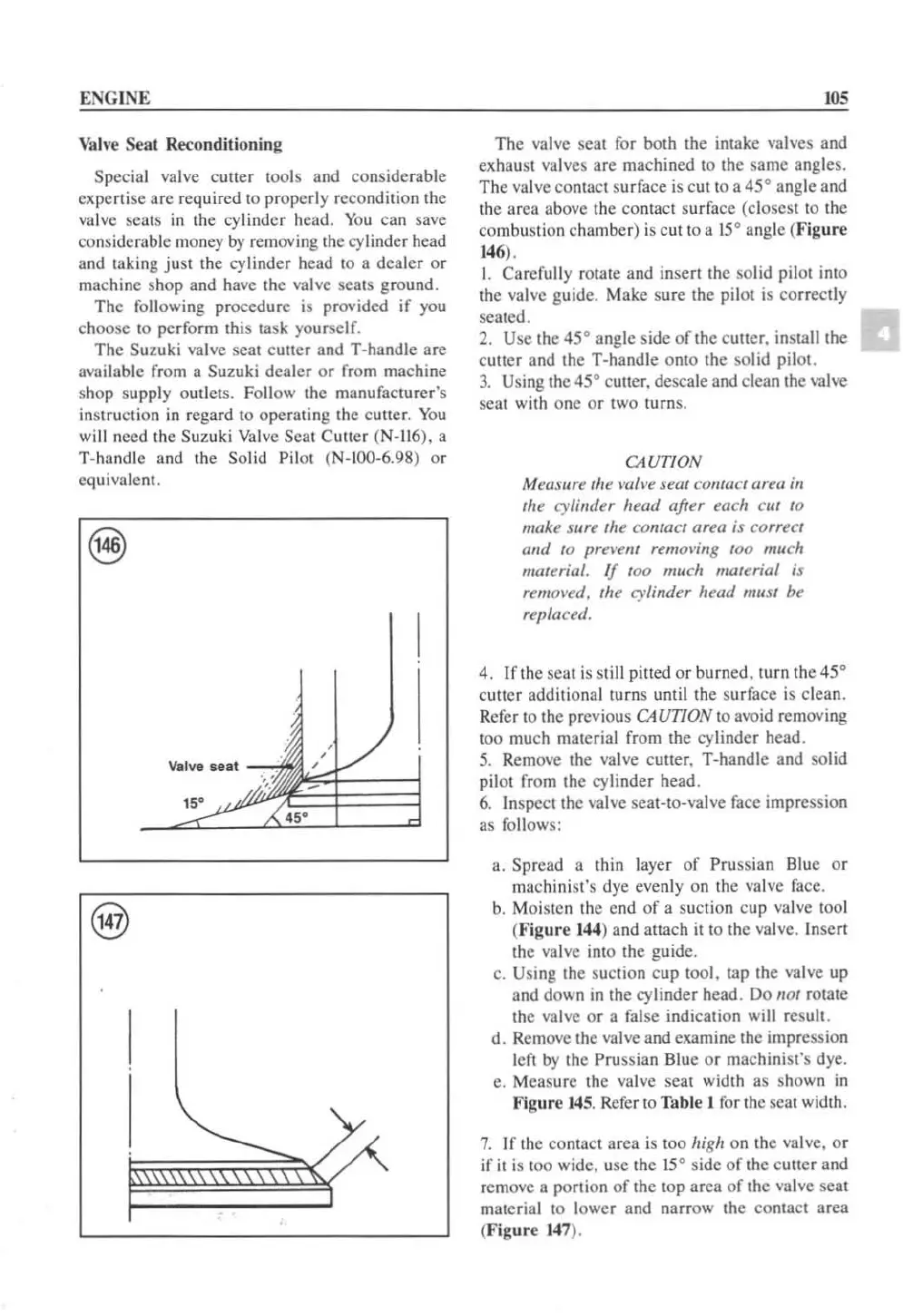
The
va
l
ve
seat
for
both the intake
va
lves and
exhaust
va
lve
s are
ma
chined to the same angles.
The
va
l
ve
co
nta
ct surface is c
ut
to
a 45° angle and
the area above the contact surface (closest to the
co
mb
ustion chamber) is c
ut
10
a 15° angle
(F
ig
ur
e
14
6),
I. Carefully rotate and insert
th
e sol
id
pilot into
the
va
l
ve
guide. Make sure the pilot
is
cor
rec
tl
y
seated.
2.
Use
th
e 45
D
angle side
of
th
e cutler. install the
cutter and the T-handle o
nt
o the sol
id
pilot.
3.
Using the
45
D
cu
tt
er. descale
and
clean the valve
sc
at
with one
or
t
wO
turn
s.
CAUTION
Measure the \'all'e seal
cO
llla
ct area
in
the cylinder head after tach cut to
make sure
th
e contact area is correct
and
to
prel'ent remol'ing too much
material. If
100
much material is
remOI
·ed. tilt cylinder heml must
bt
replacell.
4. Jfthe scat is st
ill
pitted or burned.
tu
rn the
45
D
culler additional turns until the surface is clean.
Refer
to
the pr
ev
ious C4UTION
to
avoid re
mov
i
ng
too
mu
ch material from the cylind
er
head.
5.
Rem
ove the valve
cUlle
r. T-handle and solid
pilot
fr
om the
cy
linder head.
6.
Jnspectthe
va
lve seat-to-valve
face
impression
as follows:
a.
Spread a thin layer
of
Prussian Blue or
ma
chinist's dye eve
nl
y on
th
e valve
fa
ce.
b.
Moisten the end of a suction cup v
al
ve
1001
(
Fi
g
ur
e
144
) and allach
it
to
the valve.
In
sert
the valve into the guide.
c.
Using
th
e suction cup tool. tap
th
e
va
l
ve
up
and down in
th
e cylinder head. Do
nOI
rotate
the
va
l
ve
or
a false indica
ti
on w
ill
result.
d. Remove the valve and examine the impression
le
ft
by Ihe Prussian Blue
or
machinist's dye.
e.
Measure the
va
l
ve
seat width as sh
ow
n
in
Figure
14
5. R
efe
r to Table I for
th
e seat width.
7.
If
the contact area
is
too high on the val
ve.
or
if it is t
OO
wide, use
th
e 15
D
side
of
th
e cutler and
remo
ve
a portion of
th
e top area
of
the
va
l
ve
seat
mate
ri
al
to
lower and narr
ow
the contact area
(Figure 1
47
).
 Loading...


