REAR SUSPENSION
285
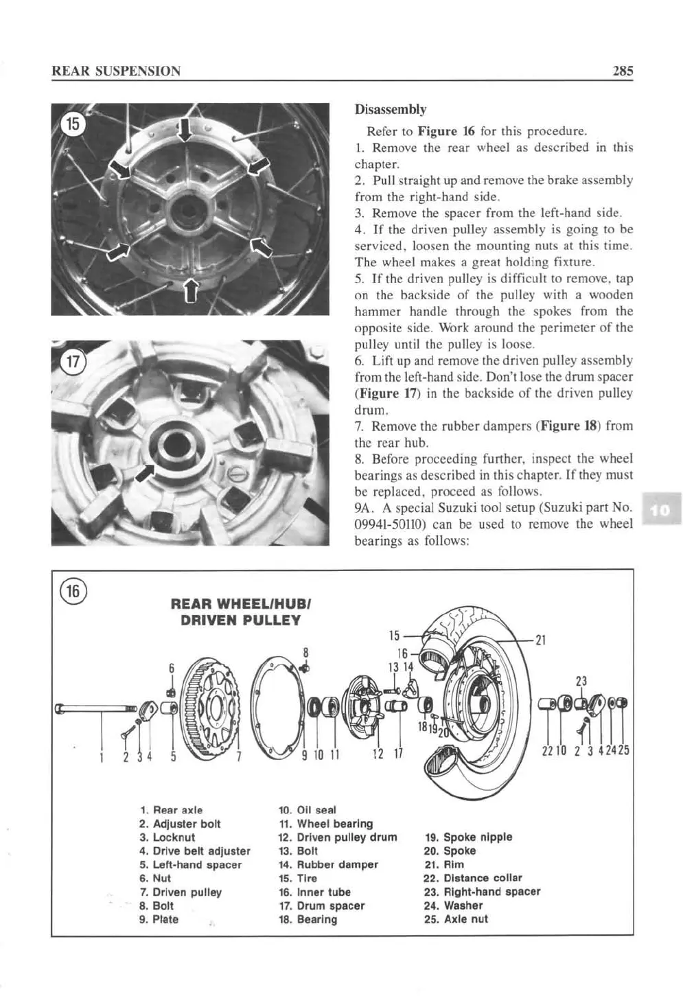
Disassembly
Refer
10
Figure
16
fo
r Ihis procedure.
I. Rem
ove
the rear wheel as desc
ri
bed in
th
is
chapler.
2.
Pull straight up and remove the brake assembly
from the right-hand side.
3.
Remove the spacer from the left-hand s
id
e.
4. If the driven pulley assembly is going to be
serviced. loosen the mounting nuts
at
this time.
The wheel makes a great holding
fi
XlUre.
5.
If the driven pulley is difficult to remove. lap
on the backside of the pulley with a wooden
hammer handle throu
gh
the
spo
k
es
from
the
opposite side. Work around the perimeter
of
the
pullcy until
the
pulley
is
loose.
6.
Lift up and remove the driven pullcy assembly
from the left-hand s
id
e. Don't lose
th
e drum spacer
(
Figure
17
)
in
the backside
of
th
e driven pulley
drum.
7.
Remove the rubb
er
damper
s (
Figure
18
) from
the rear hub.
8.
Before proceeding further, inspect the wheel
bearings as described in
this chapter.
If
they must
be repla
ced,
proceed as follow
s.
9A. A special Suzuki 1001 setup
(S
uzuk i part No.
09941-50110)
can be used 10 remove the wheel
bearings as follows:
REAR WHEEL/HUB/
DRIVEN PULLEY
1. Rear axte 10.
011
seal
2. AdJualer
bolt
11
. Wheel bearing
3. Locknut
12
. Driven pulley
drum
19. Spoke nipple
4.
Drive belt adjuster 13.
Boll
20. Spoke
5.
left·hand
spacer 14. Rubber damper
21
. Rim
6.
Nut
15. Tire
22. DIstance
collar
7.
Dr
iven pulley 16.
Inner
tube
23. Rlghl.hand spacer
8.
Bolt
17.
Drum spacer 24. Waaher
9. Ptate
18
. Bearing
25.
Axle
nut
 Loading...


